
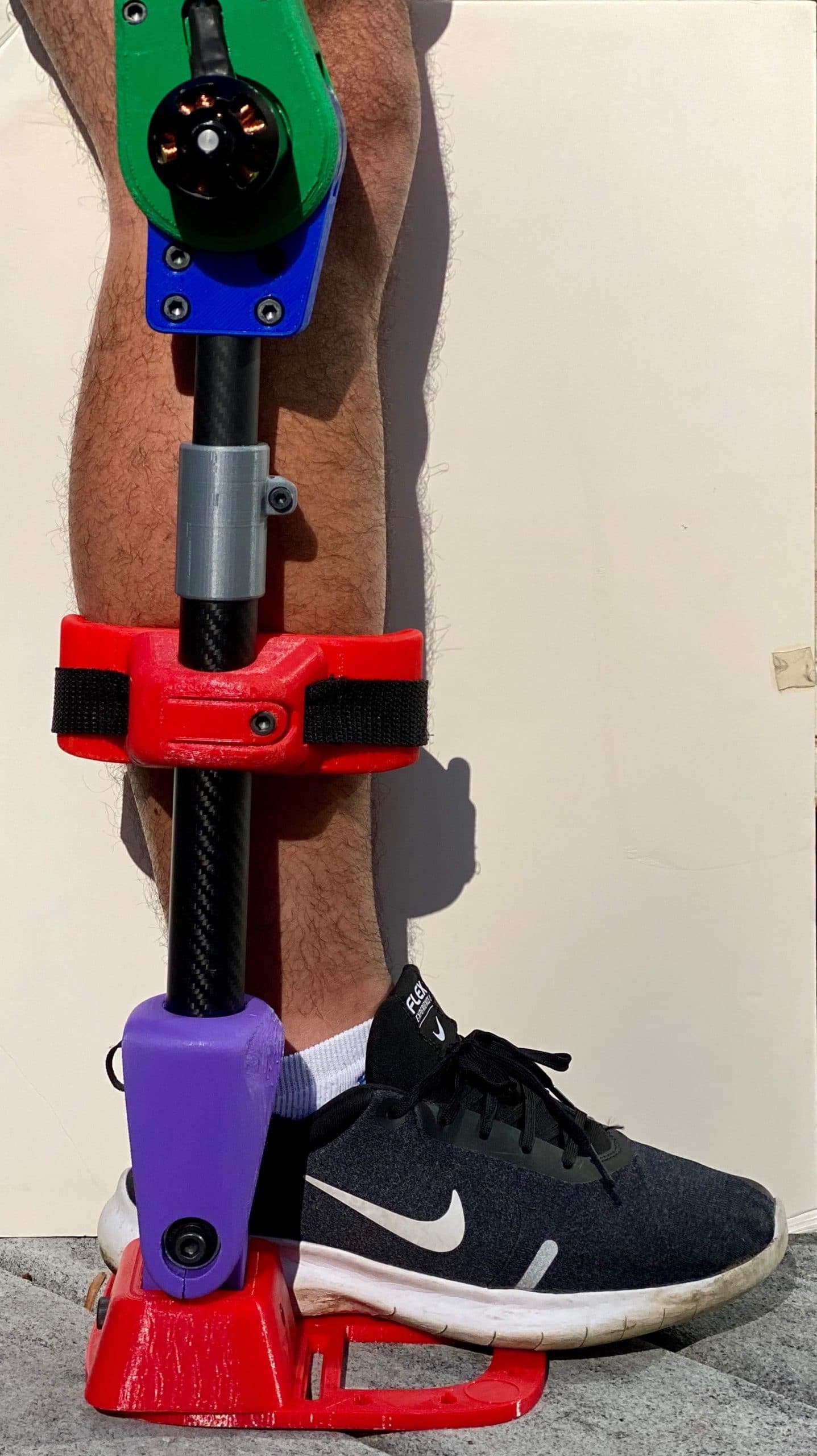
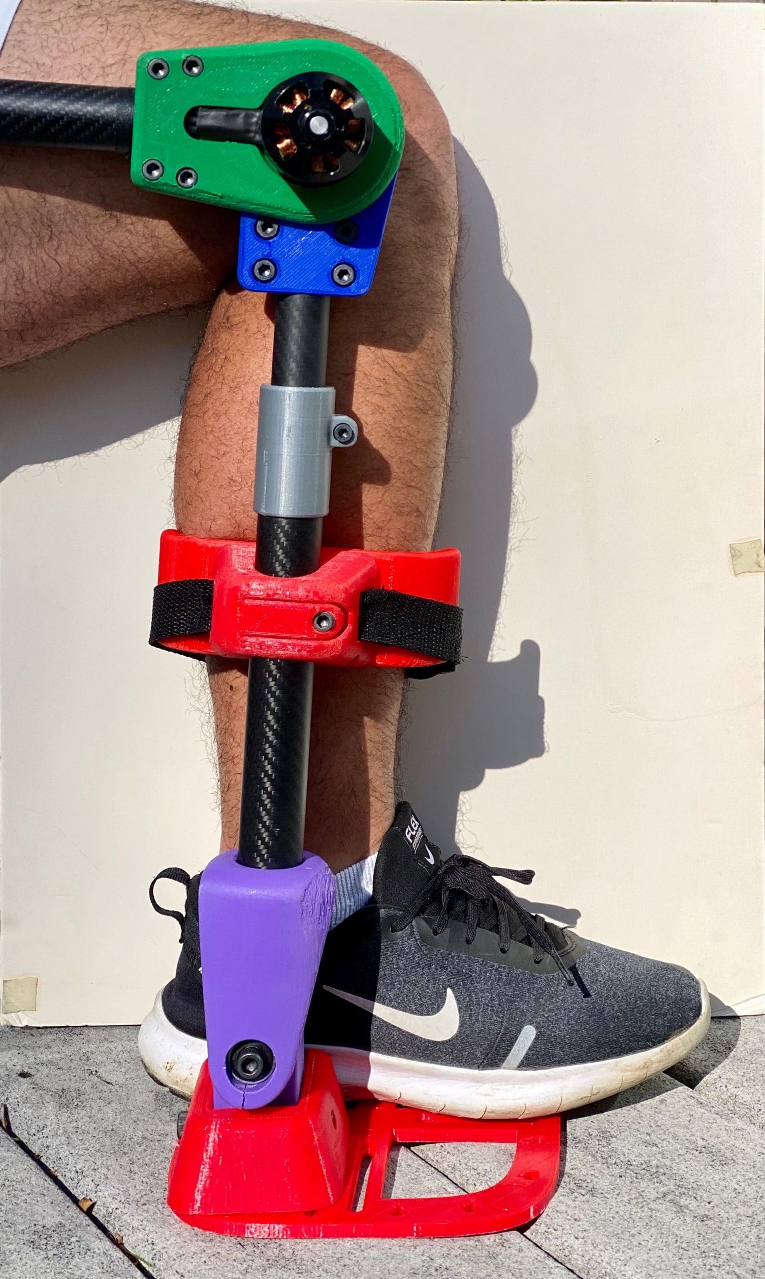
StrydLight™ frame encompasses adjustable structural members, comfortable braces, and passive joints. Carbon fiber materials and plastic parts provide a light and low-inertia infrastructure for the StryDrive™ actuator and StrydSense™ control system.
Revision History
Scroll down to learn about the process
Revision 3 – Title
- Need to look at iWalk
- Rubber Bushings
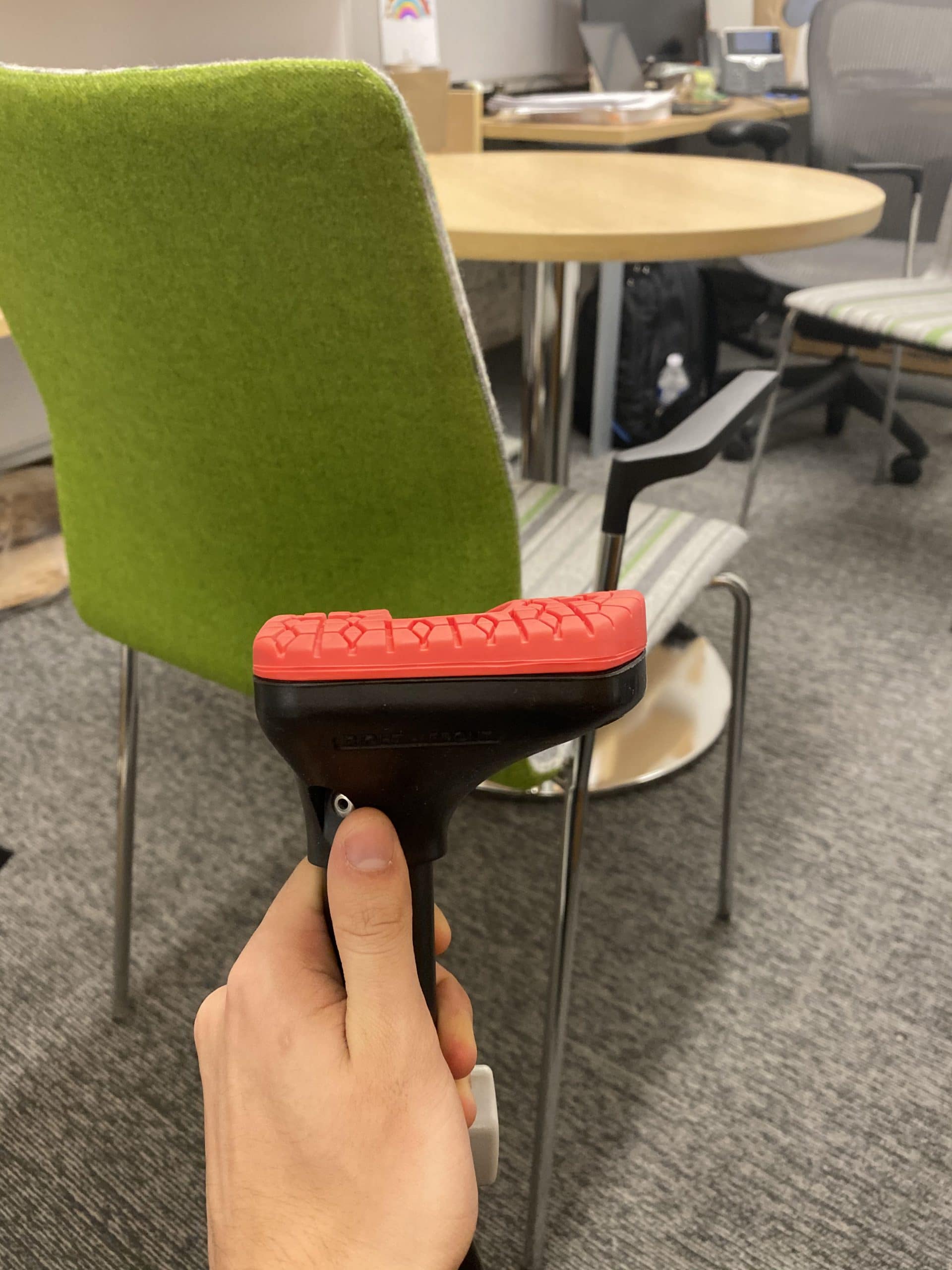
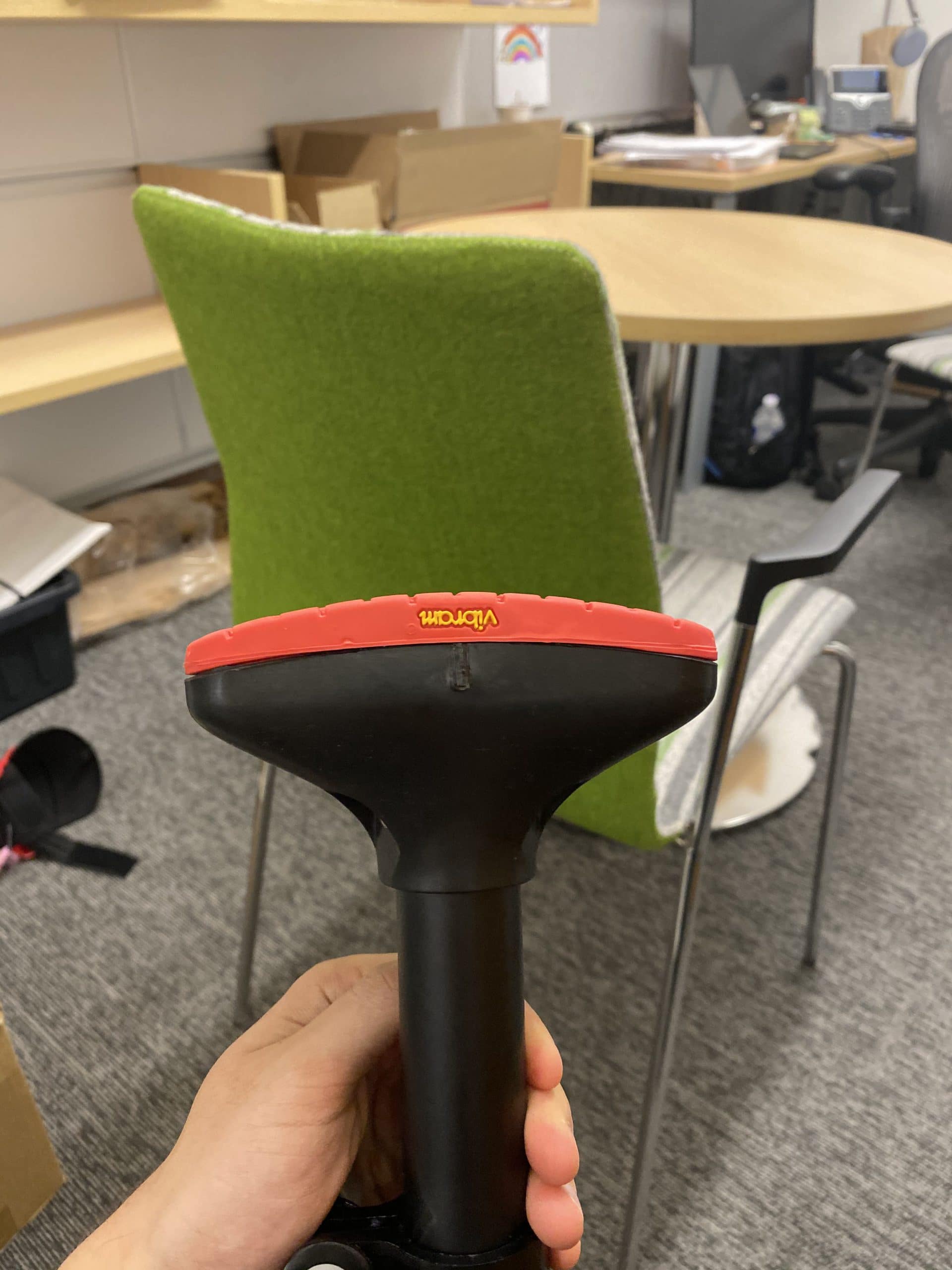
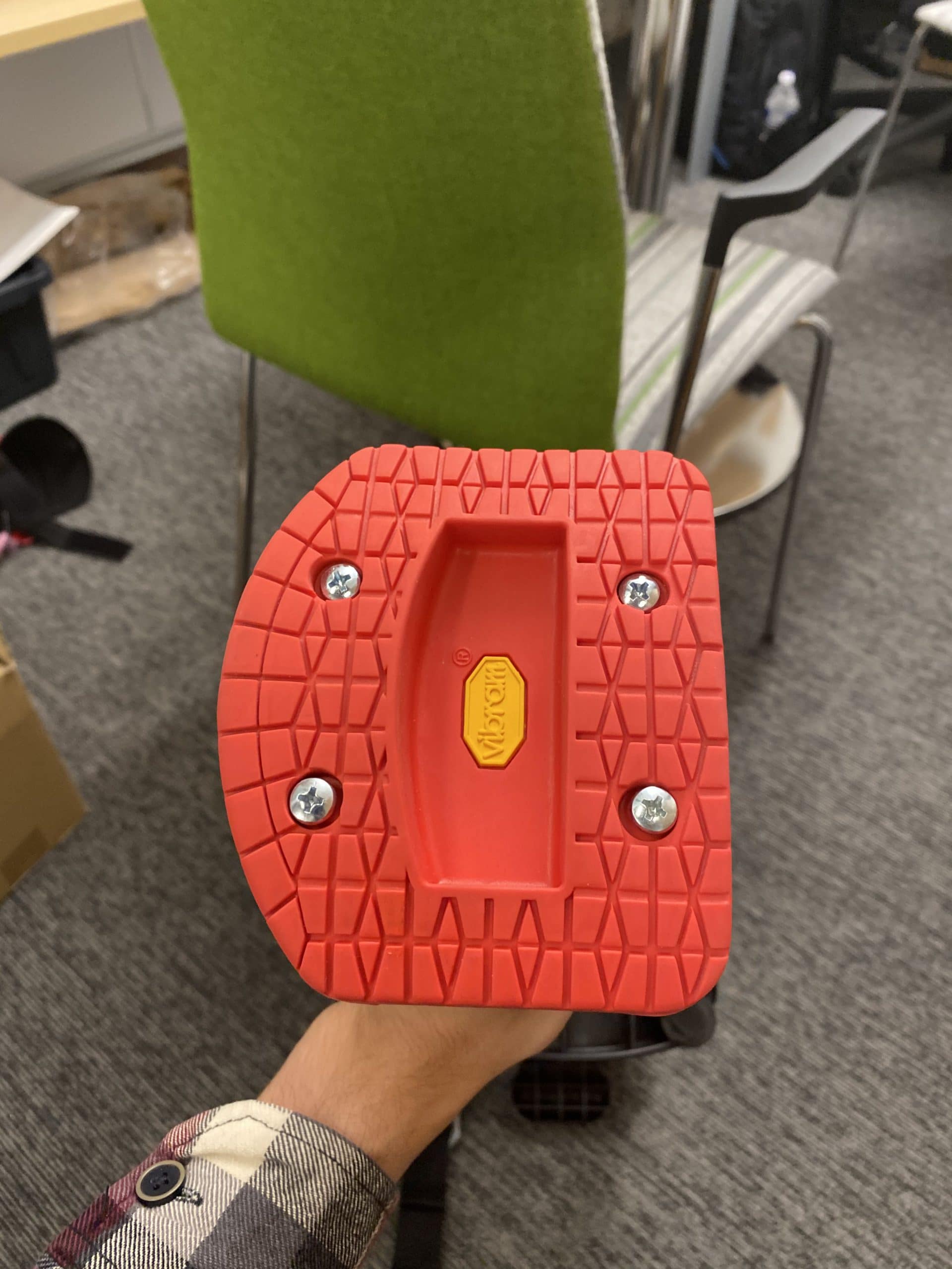
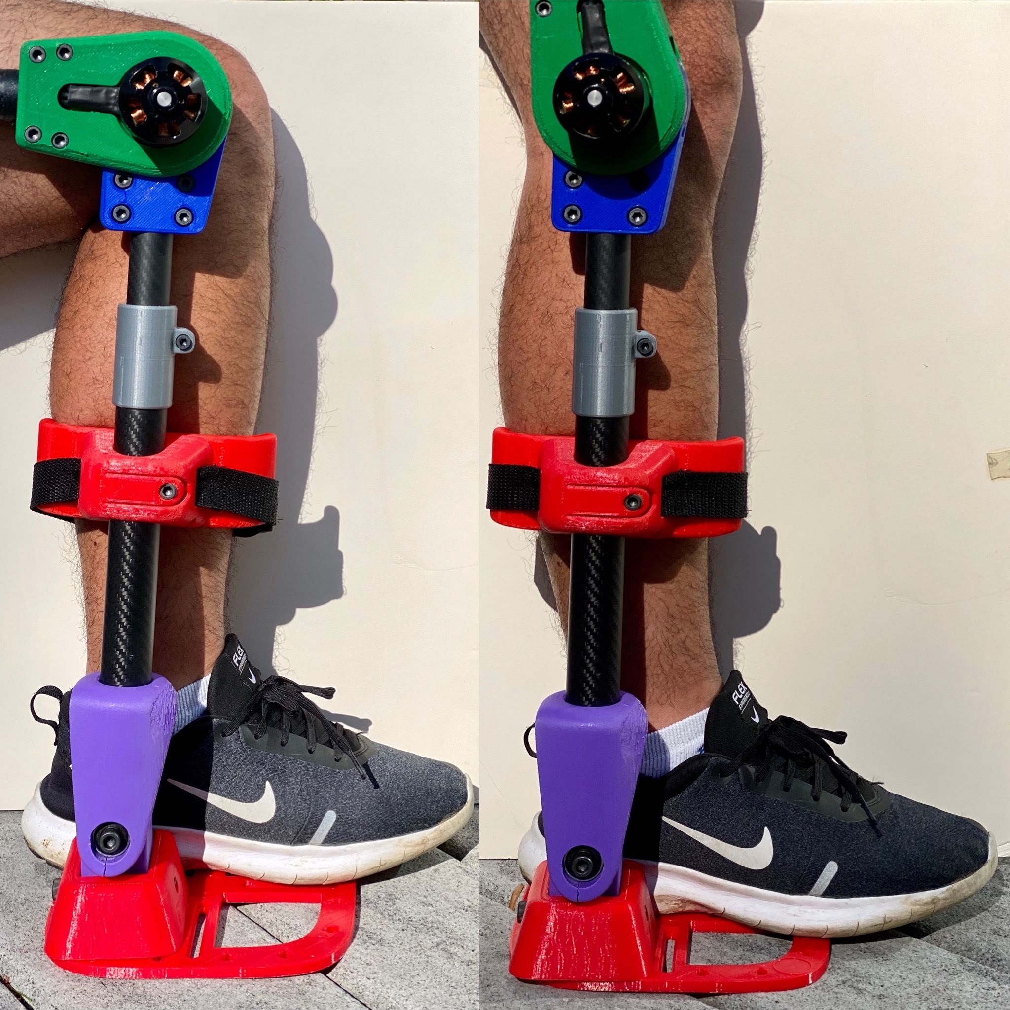
- Shoe-Sandal Version
Design Developments
- 1.0mm cylindrical ribs to secure carbon fiber tubes
- Gearbox Output separated into acrylic and PLA components
Electrical Developments
- Rotary encoder position on PCB corrected.
- oDrive startup protocol configured.
Manufacturing Developments
- Laser Cut 5.5mm Cast Acrylic Gearbox
- Laser Cut 12.80mm Cast Acrylic Gearbox
- FDM 3D printed housing
- SLA 3D printed CAM shaft
Design Developments
- Replacing output gear ring with 37 independent pins and rollers.
- Replaced output bearings with brass bushings.
- Preliminary material selections.
Manufacturing Developments
-
- Submitted 2D and 3D CAD to Machinists
- Design For Manufacturing Complete
- 7075-T6 Aluminum Anodized Exterior
- S45C (AISI 1045) Steel Gear
- Brass Bushings


Revision 2 – Title
- Need to look at iWalk
- Rubber Bushings
- Shoe-Sandal Version
Design Developments
- 1.0mm cylindrical ribs to secure carbon fiber tubes
- Gearbox Output separated into acrylic and PLA components
Electrical Developments
- Rotary encoder position on PCB corrected.
- oDrive startup protocol configured.
Manufacturing Developments
- Laser Cut 5.5mm Cast Acrylic Gearbox
- Laser Cut 12.80mm Cast Acrylic Gearbox
- FDM 3D printed housing
- SLA 3D printed CAM shaft
Design Developments
- Replacing output gear ring with 37 independent pins and rollers.
- Replaced output bearings with brass bushings.
- Preliminary material selections.
Manufacturing Developments
-
- Submitted 2D and 3D CAD to Machinists
- Design For Manufacturing Complete
- 7075-T6 Aluminum Anodized Exterior
- S45C (AISI 1045) Steel Gear
- Brass Bushings

")
")
")
")
")
")


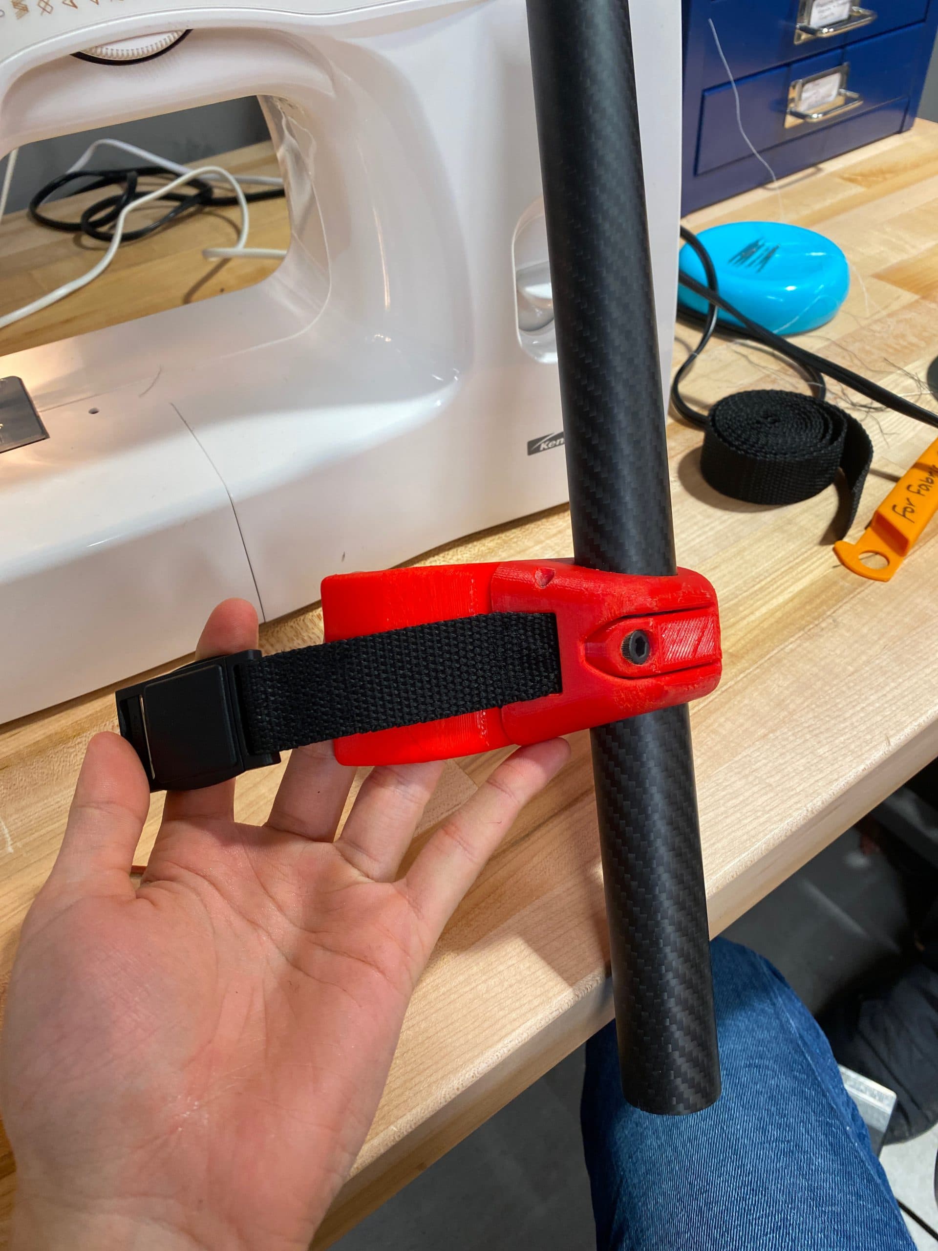
Revision 1 – Optimized Mount + Interfaces + Basic ankle
- Fixed tolerances and range of motion
- Have made CAM but need to fabricate.
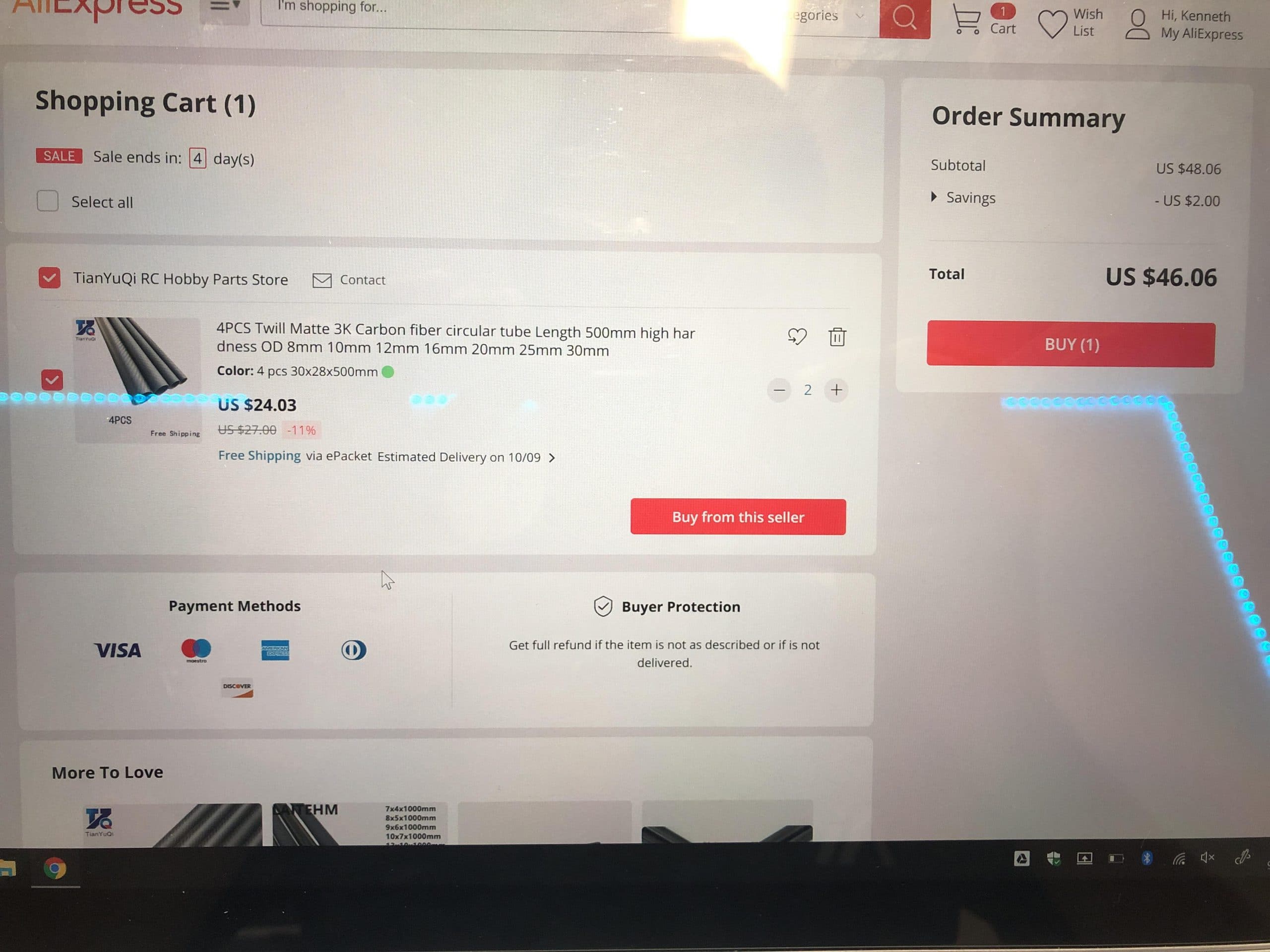
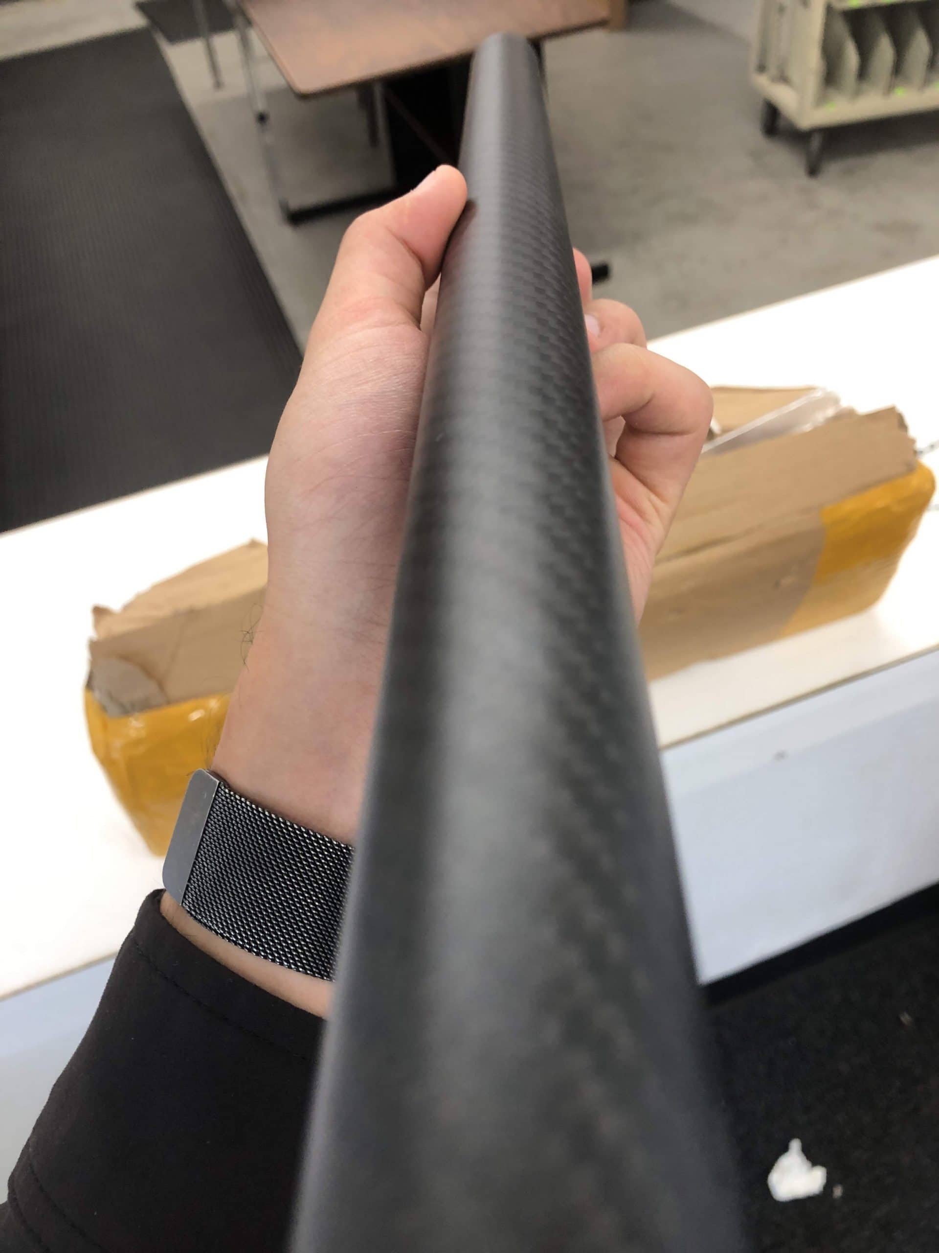
- Will CF tubes ever be delivered?
- Revised Body Interface
- C shape as designed earlier.
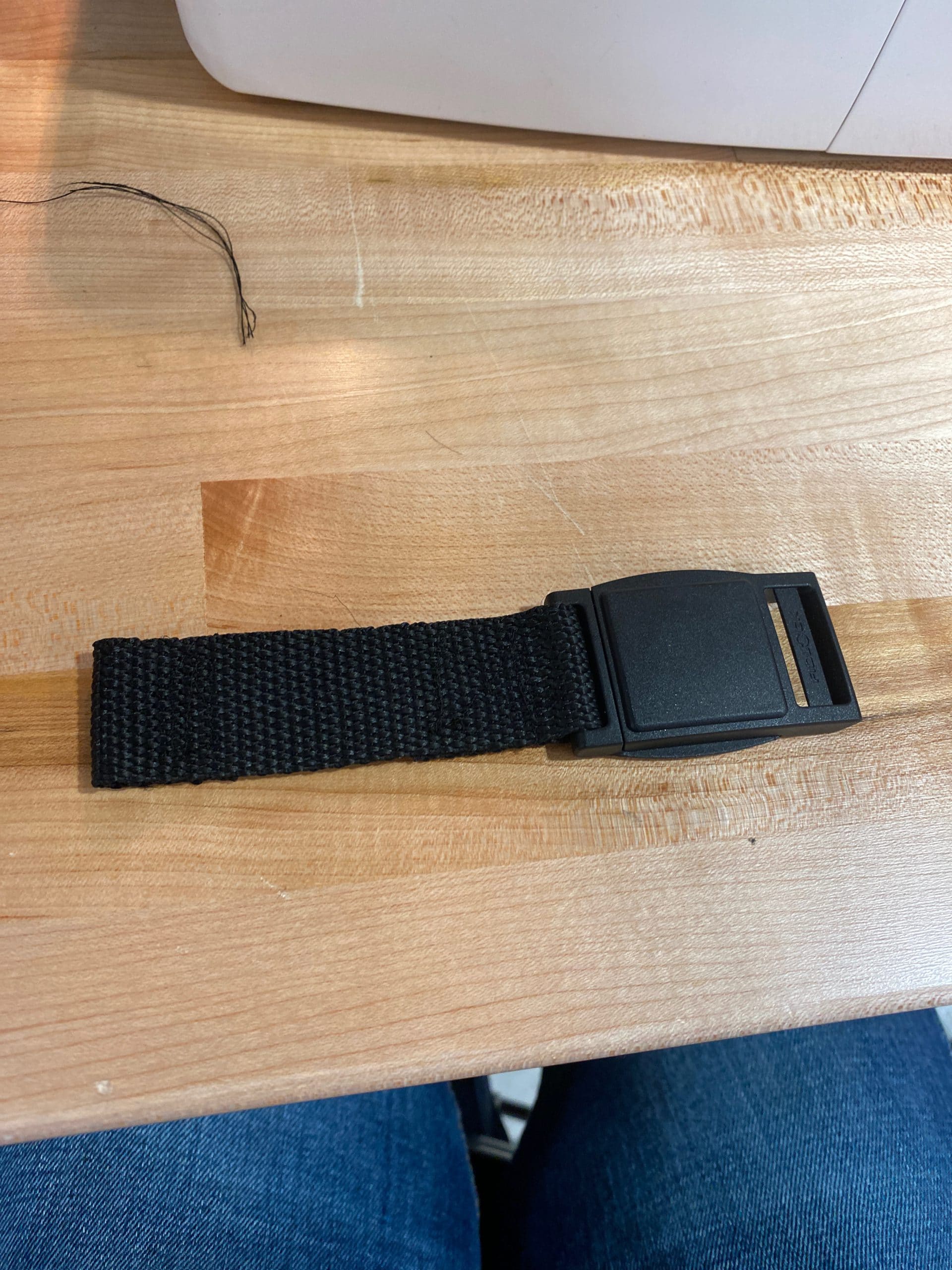
- Added FiddleLock Strap
- Sewing machine fun!
- Added Velcro
- Sewing machine failure.
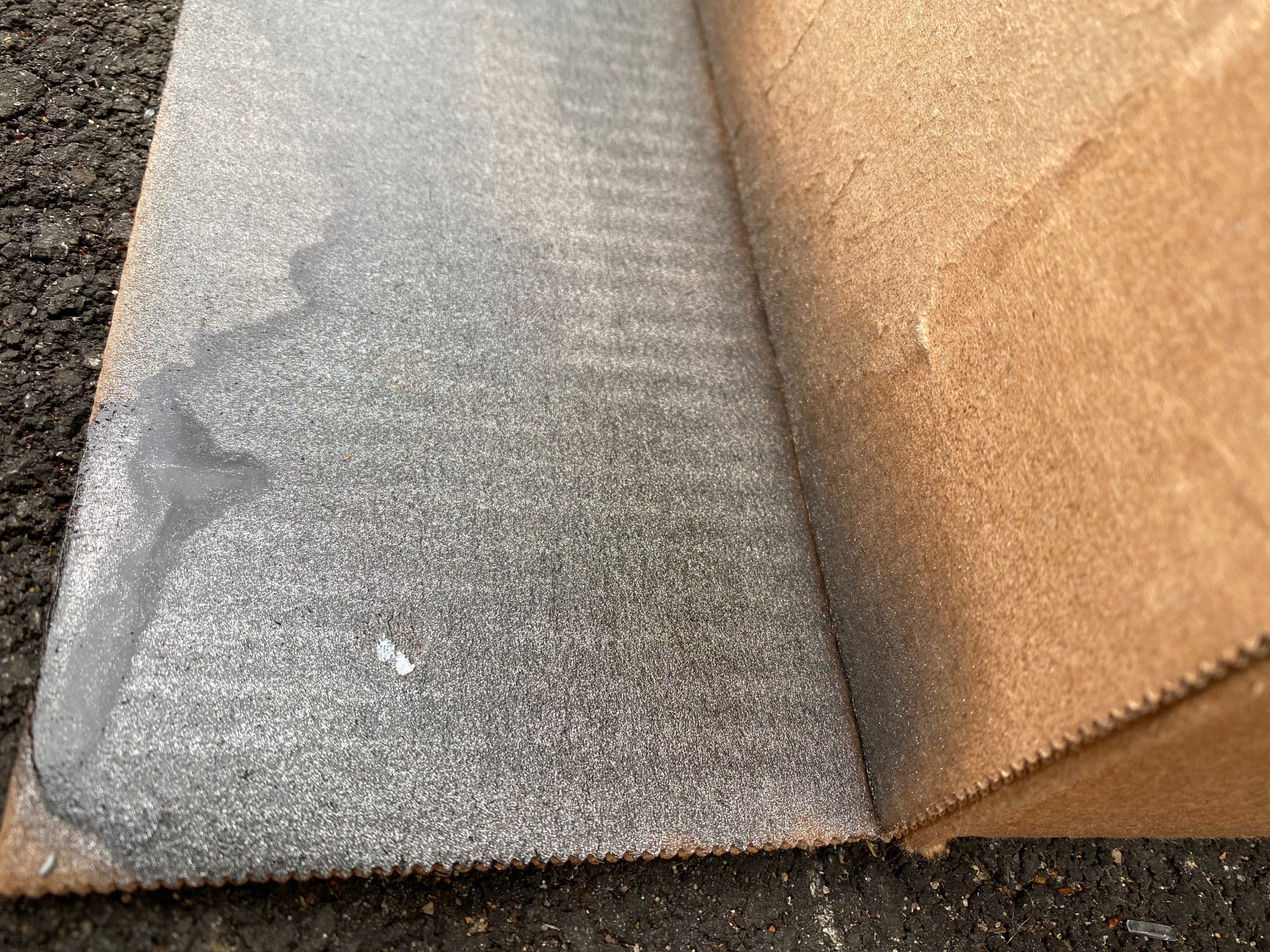
- Nylon Body Interface Cover.
- Cut the end off a legging, edge sewing.
-
- Update the design of the thigh pads and sketch out Neoprene Covers.\r\n\r\nWork on knee joint + actuator integration.
Design Developments
- 1.0mm cylindrical ribs to secure carbon fiber tubes
- Gearbox Output separated into acrylic and PLA components
Electrical Developments
- Rotary encoder position on PCB corrected.
- oDrive startup protocol configured.
Manufacturing Developments
- Laser Cut 5.5mm Cast Acrylic Gearbox
- Laser Cut 12.80mm Cast Acrylic Gearbox
- FDM 3D printed housing
- SLA 3D printed CAM shaft
Design Developments
- Replacing output gear ring with 37 independent pins and rollers.
- Replaced output bearings with brass bushings.
- Preliminary material selections.
Manufacturing Developments
-
- Submitted 2D and 3D CAD to Machinists
- Design For Manufacturing Complete
- 7075-T6 Aluminum Anodized Exterior
- S45C (AISI 1045) Steel Gear
- Brass Bushings

")


")
")


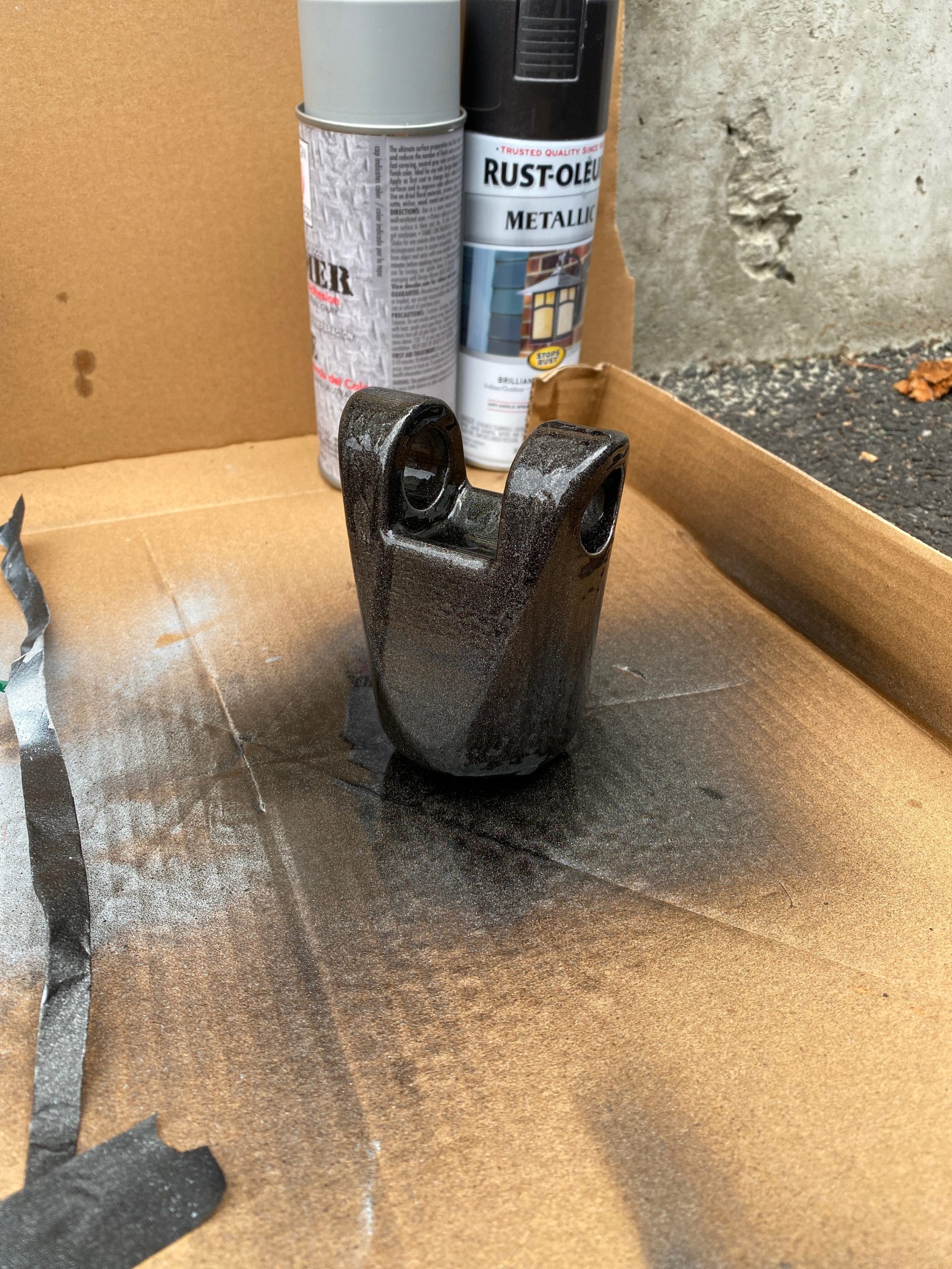
Revision 0 – Title
- Optimized 3D print
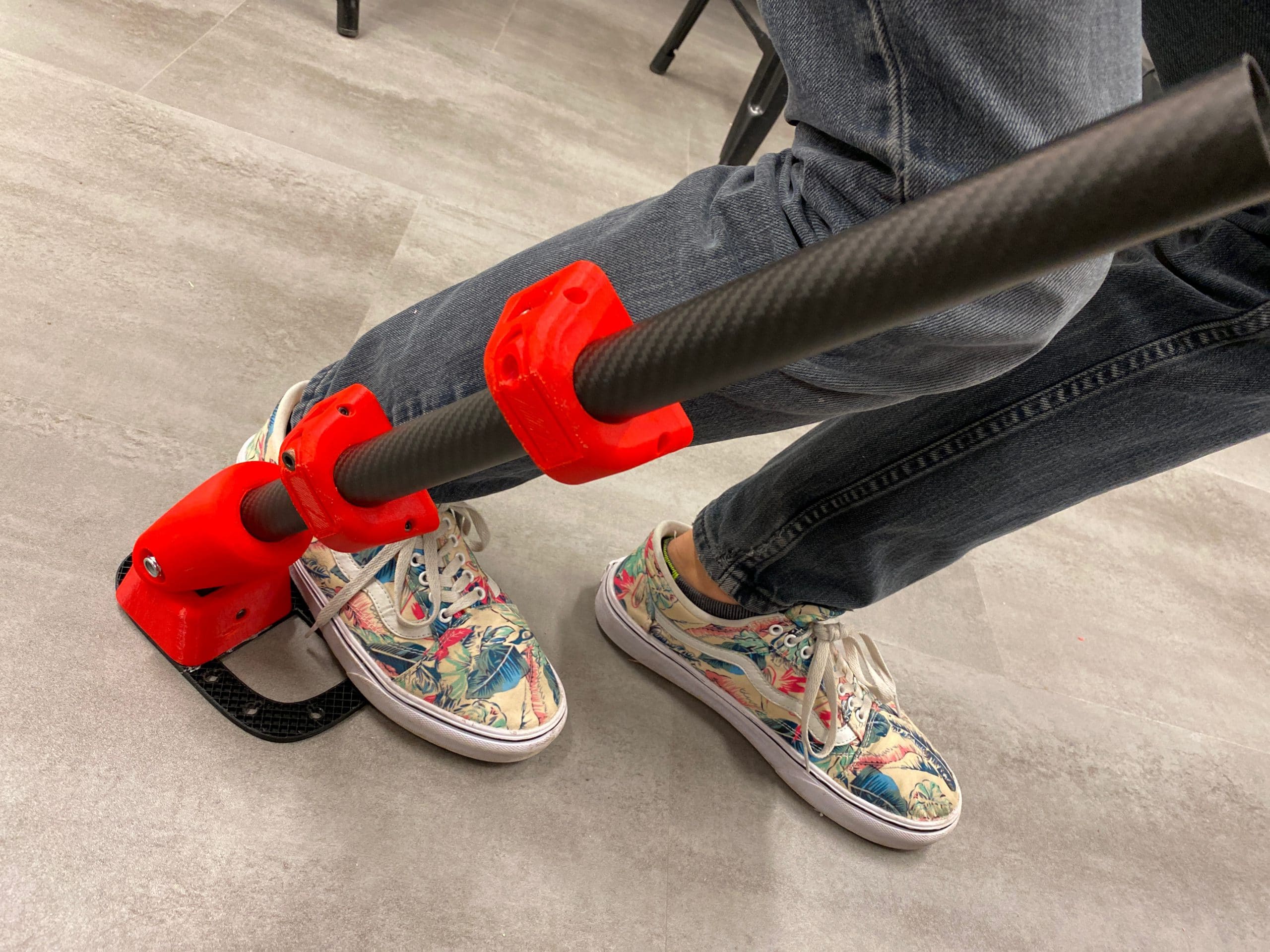
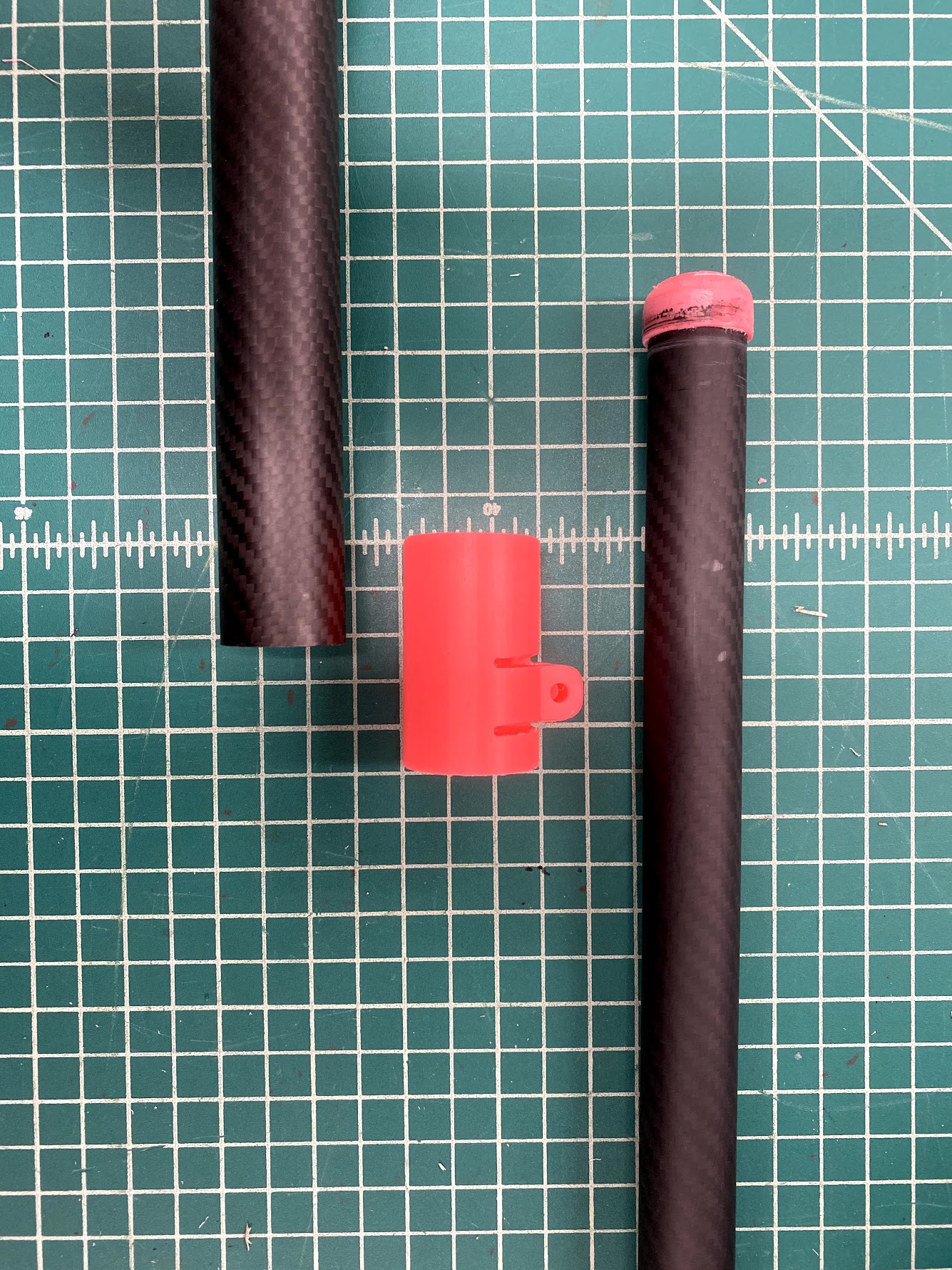
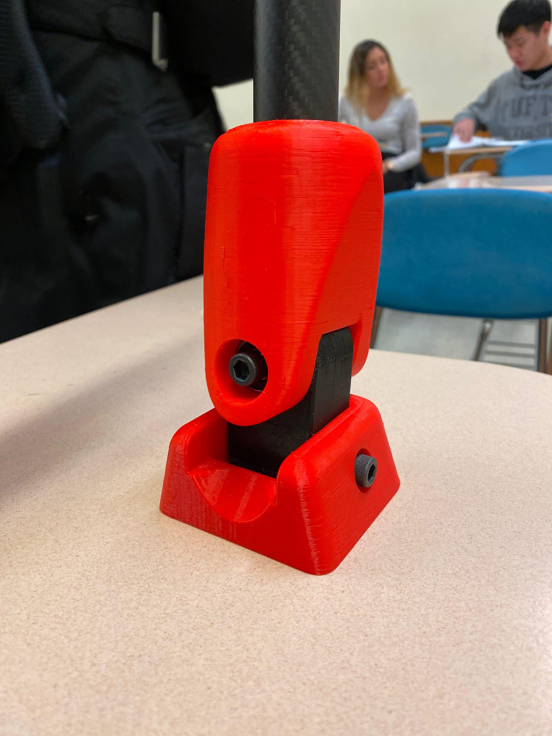
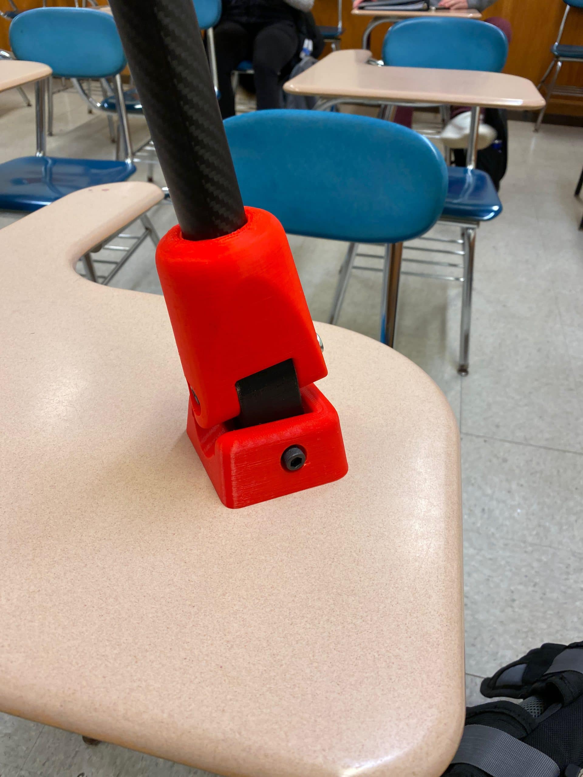
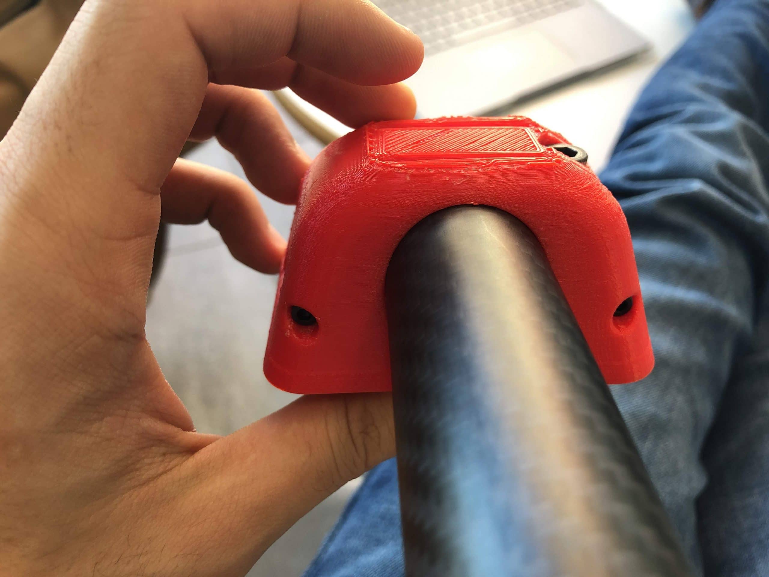
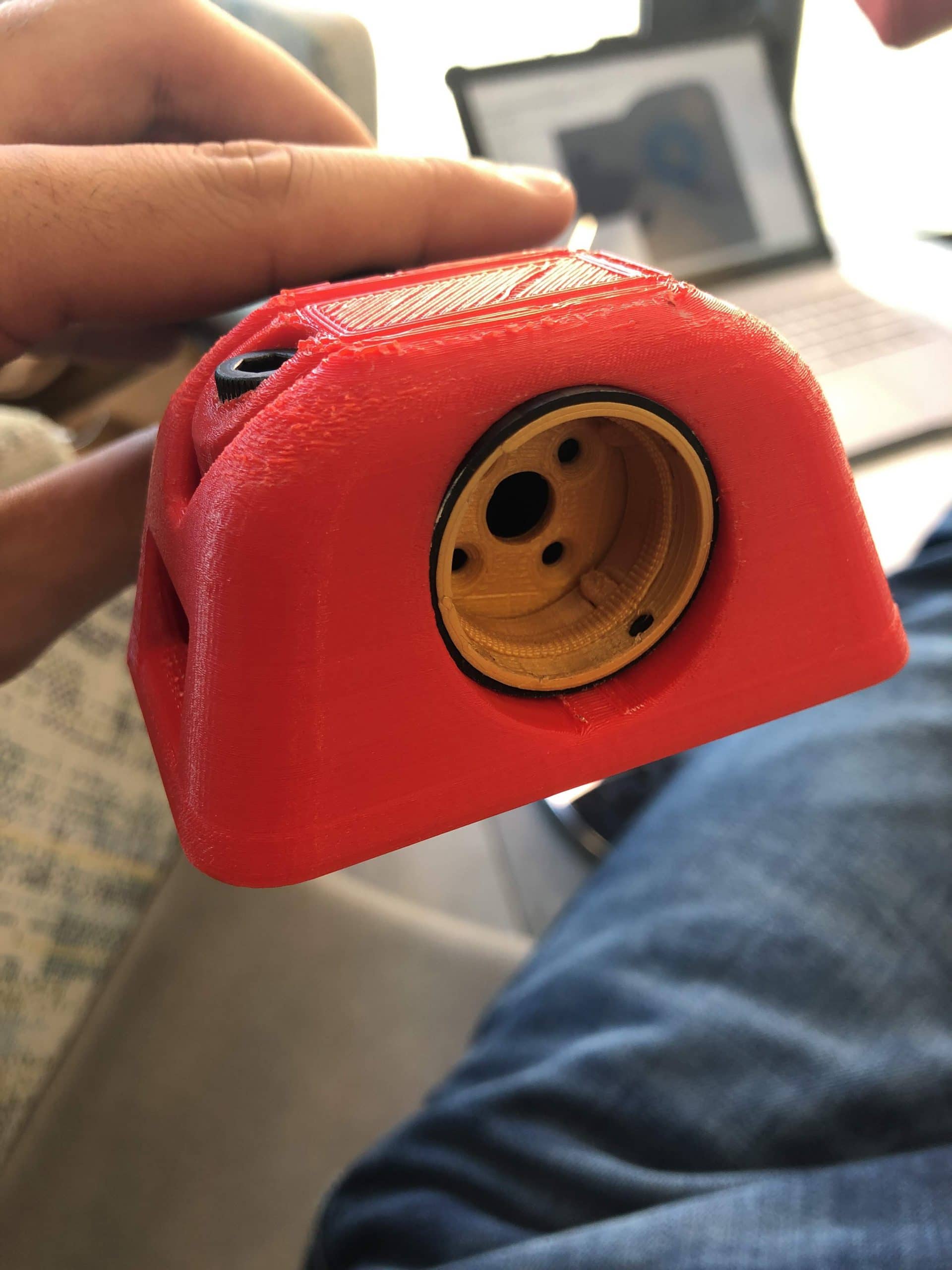
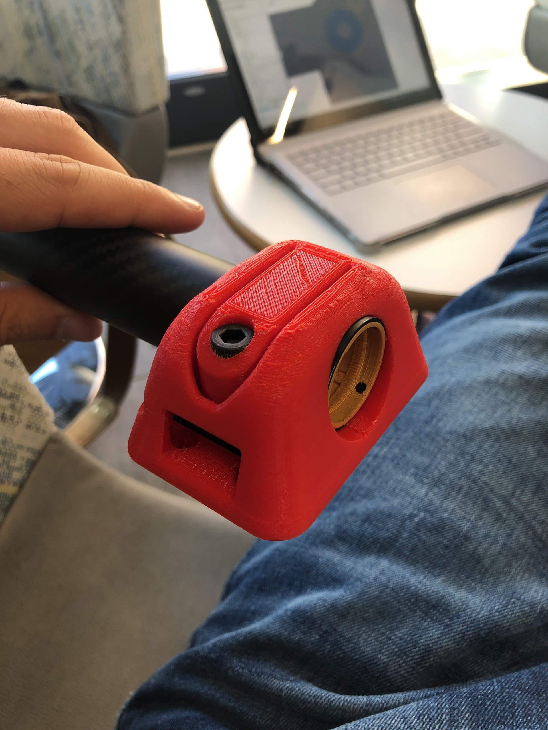
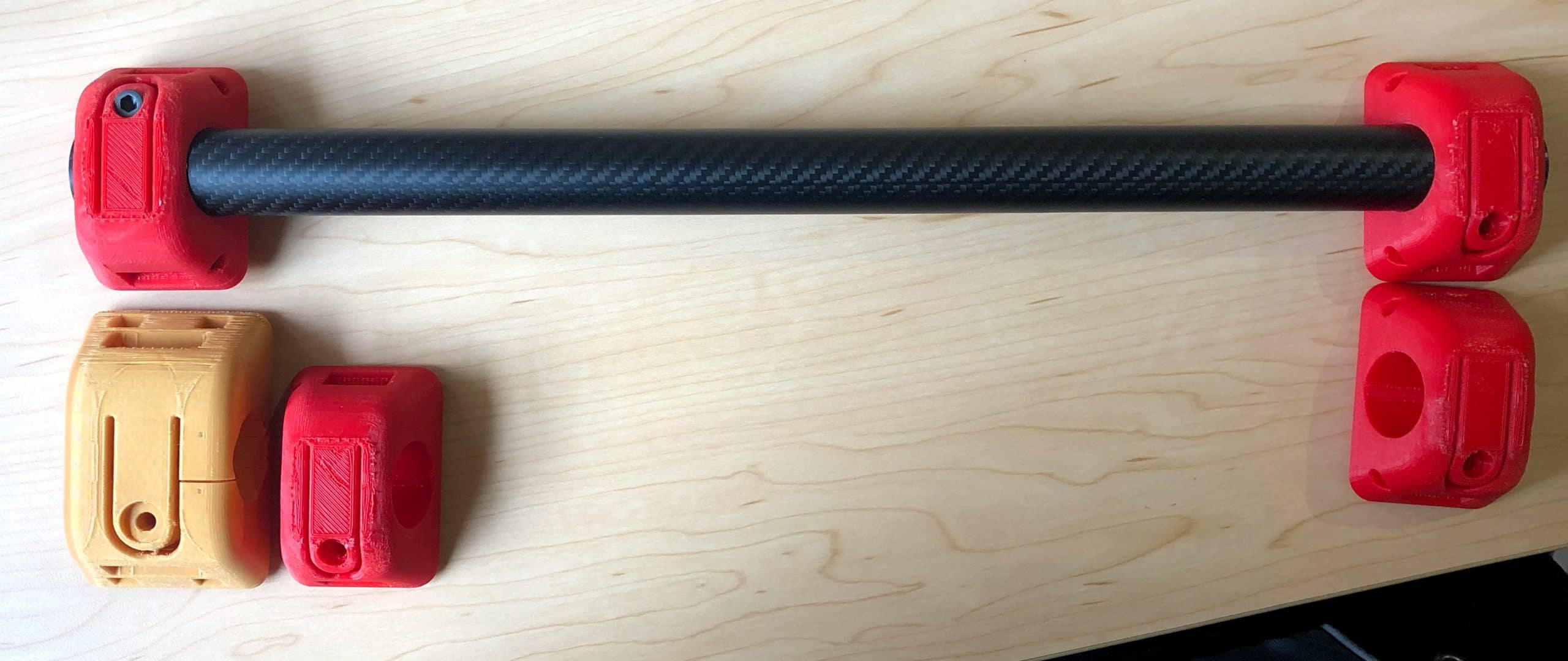
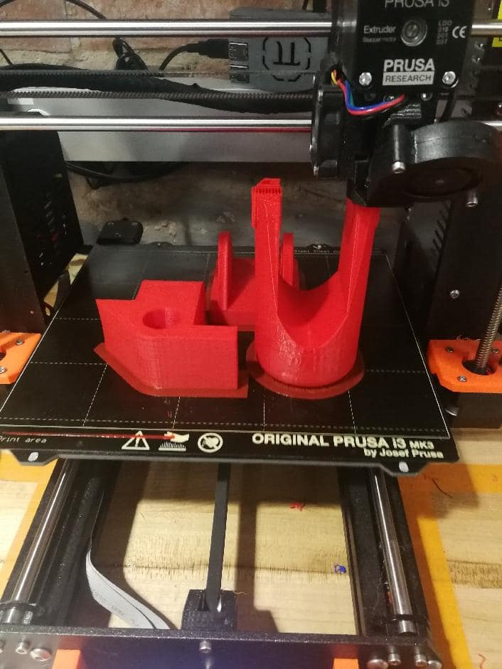
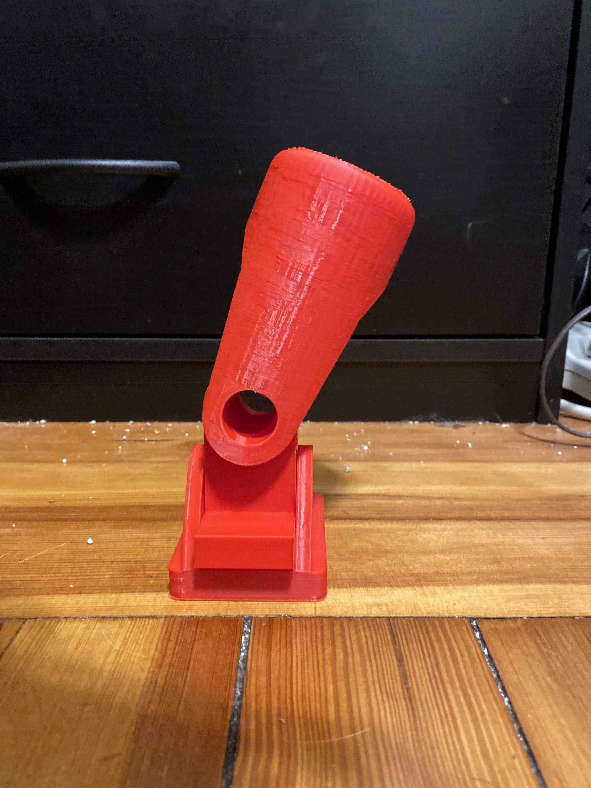
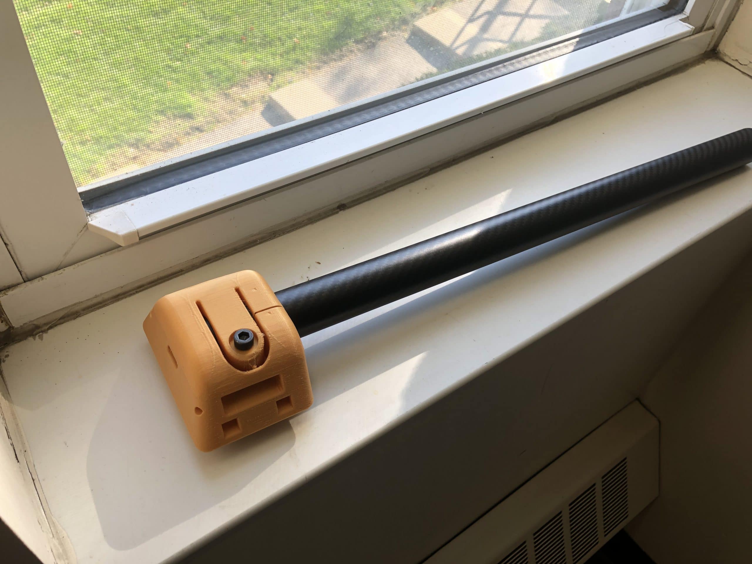
- The original design I envisioned for the frame was substantially overbuilt. I preserved many of its innovative features in my revised design:\r\n\r\nShifting to a single carbon fiber tube resulted in a volumetric reduction. In this revision, three versions of the \”Tube Mount\” are depicted – a power and data cable slot, a gearbox mount (featuring the 180mm wide thigh pad), and a mid tube mount (featuring the 150mm wide thigh pad). The thigh pad parts will later feature a washable, neoprene cover to ensure operator comfort as well as thermal insulation from the plastic and carbon fiber parts which can get cold.
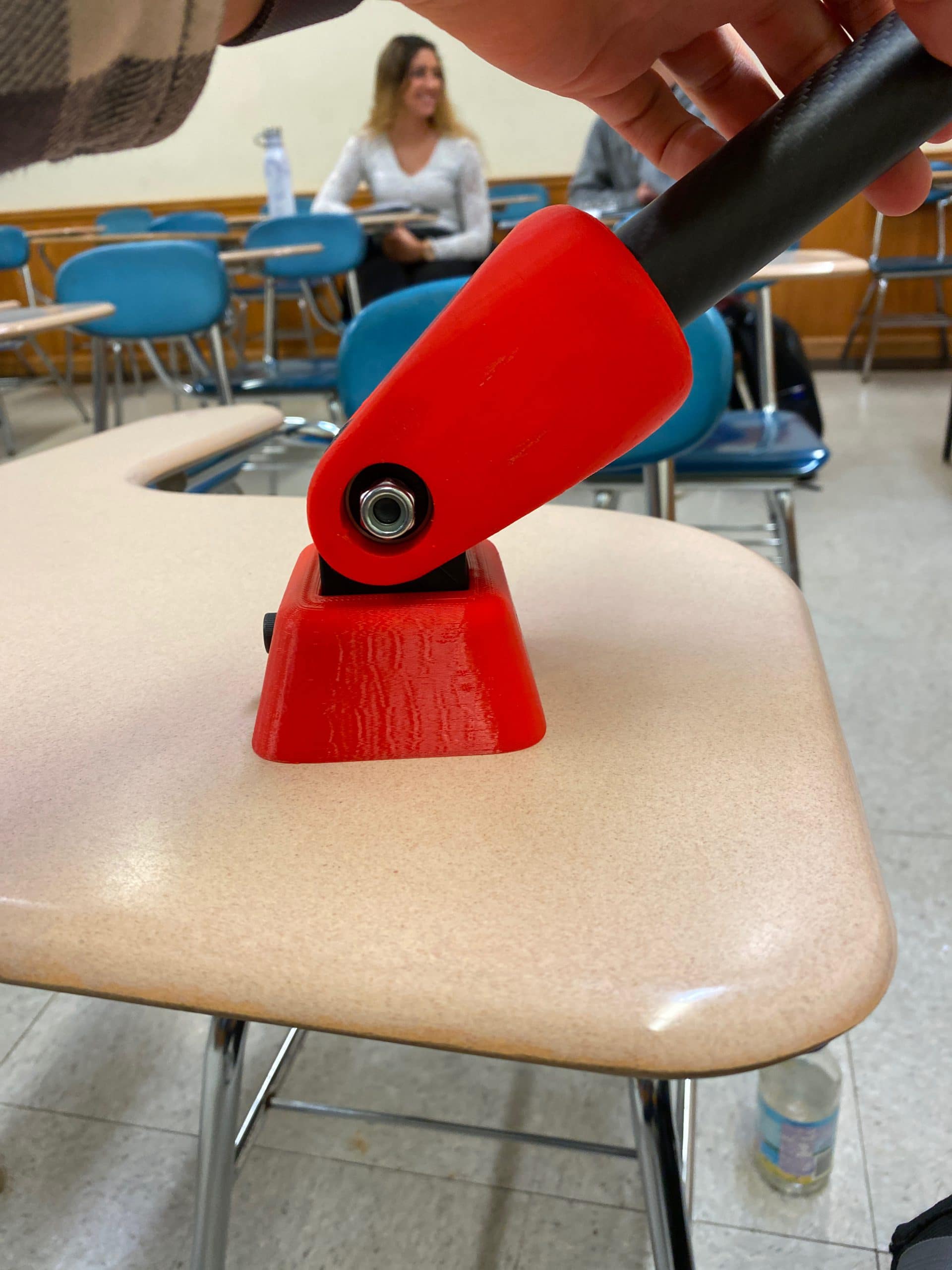
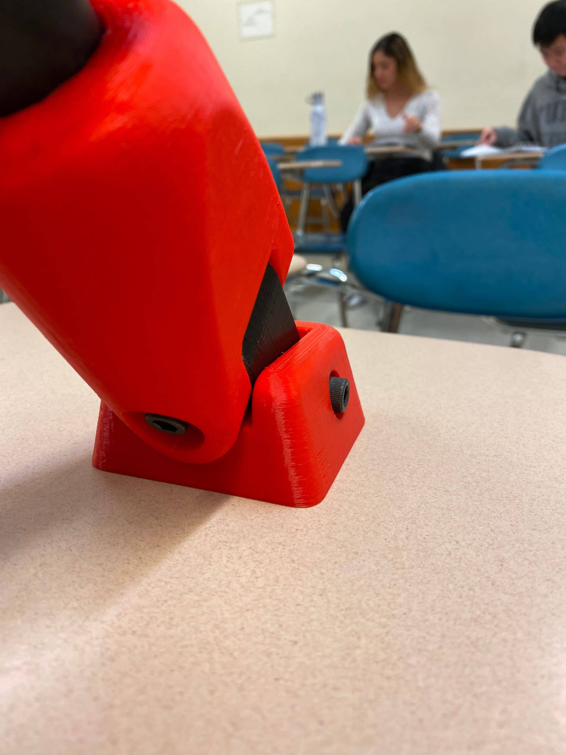
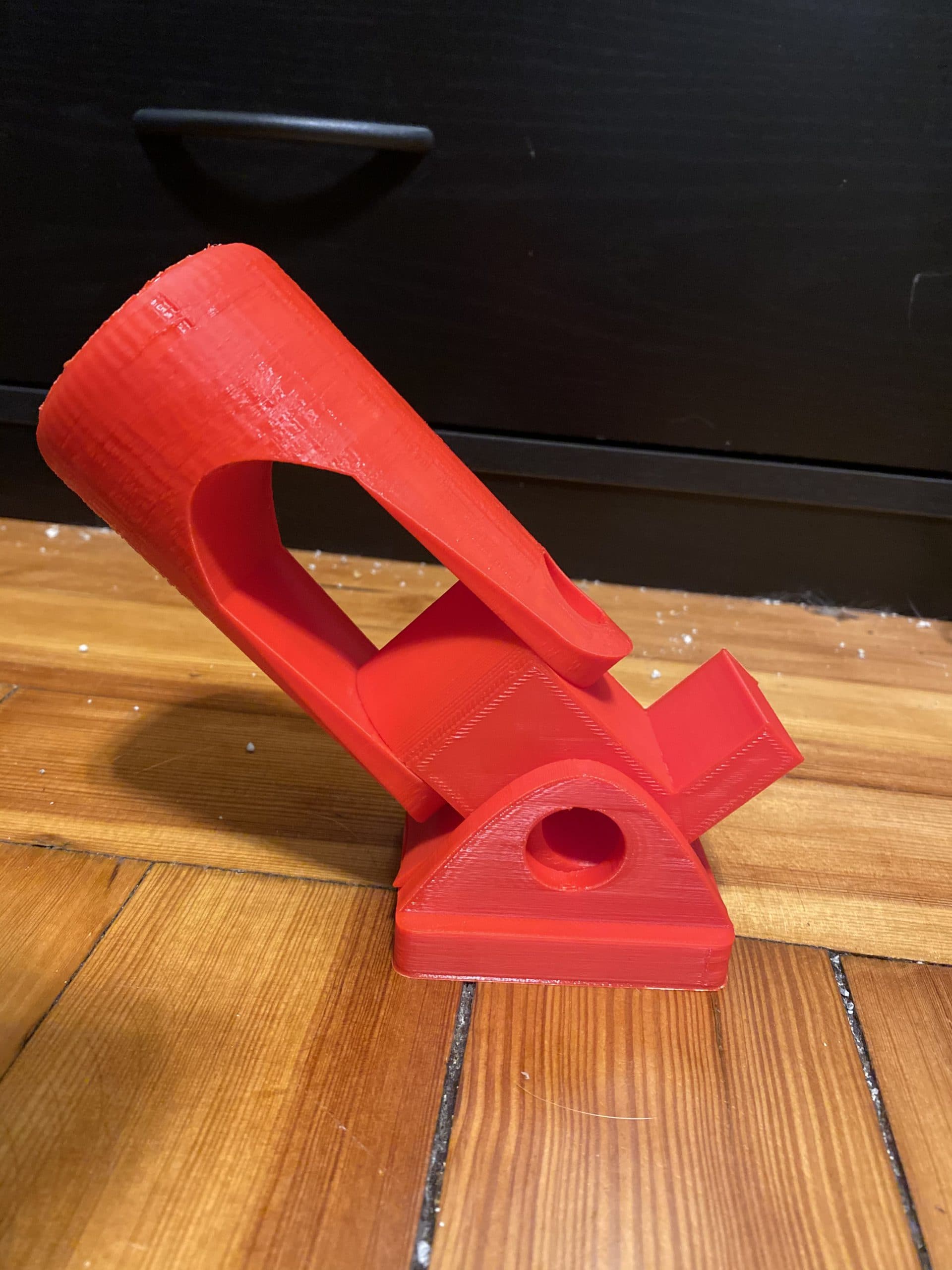
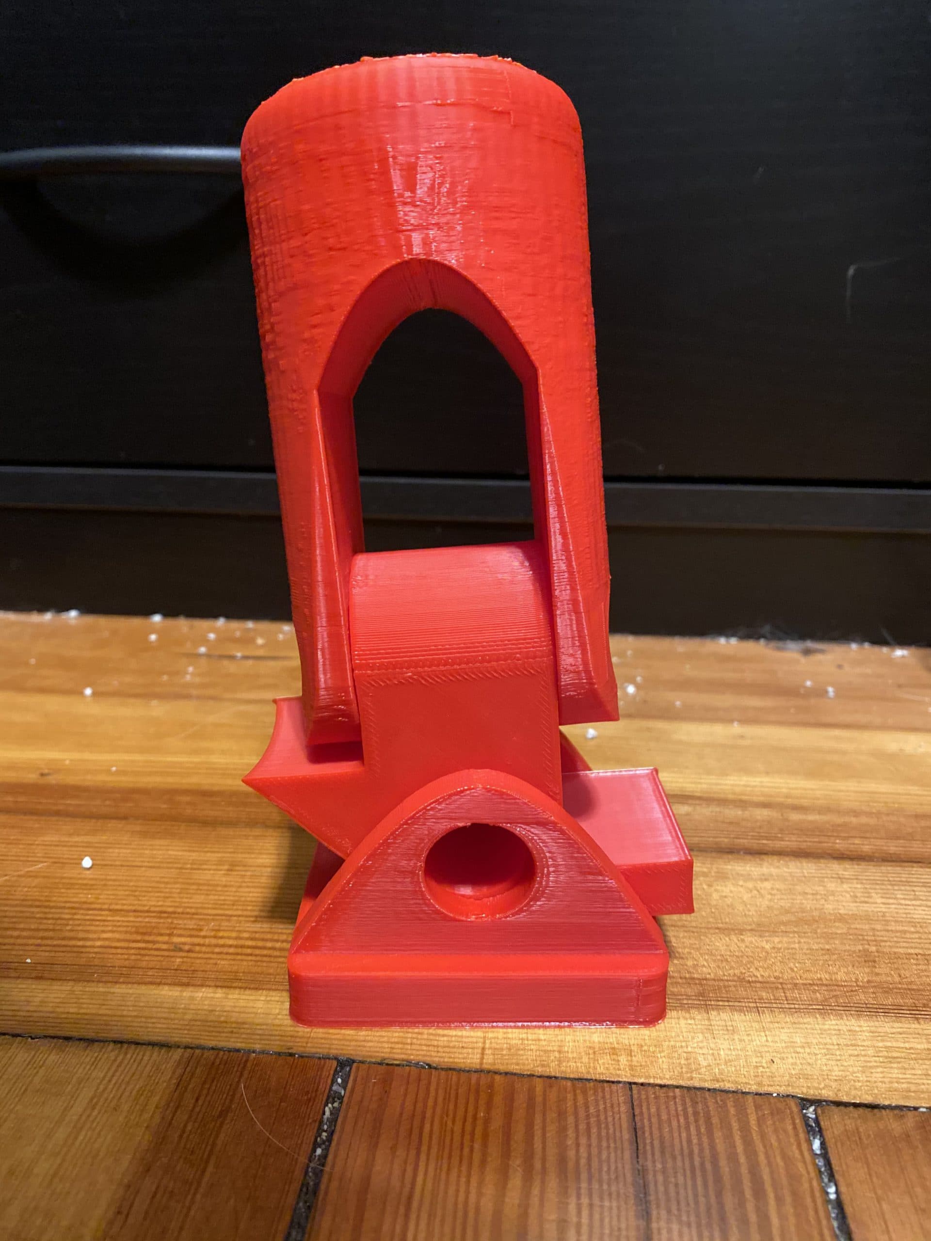
- I am dissatisfied with this version because it is too large, the surfaces have too many interruptions, and the body cracked due to printing tolerance and tube diameter. I plan to revise this part to consolidate unwieldy features and reduce the overall footprint.
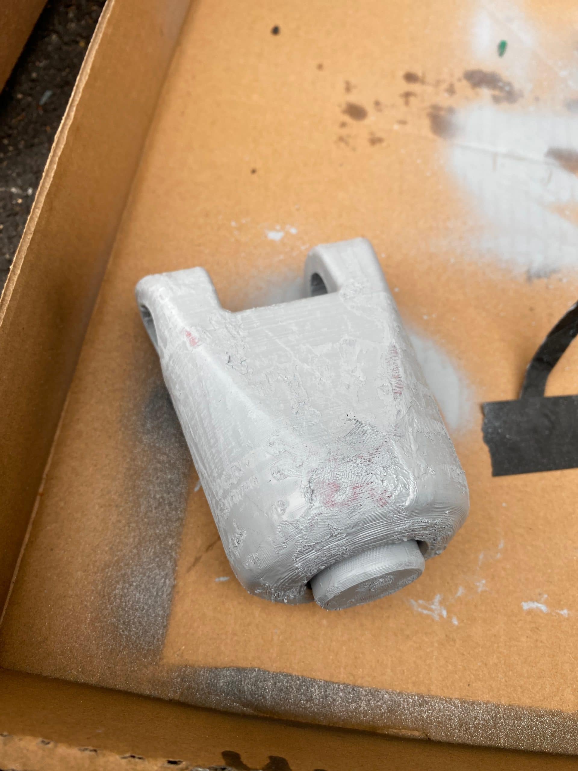
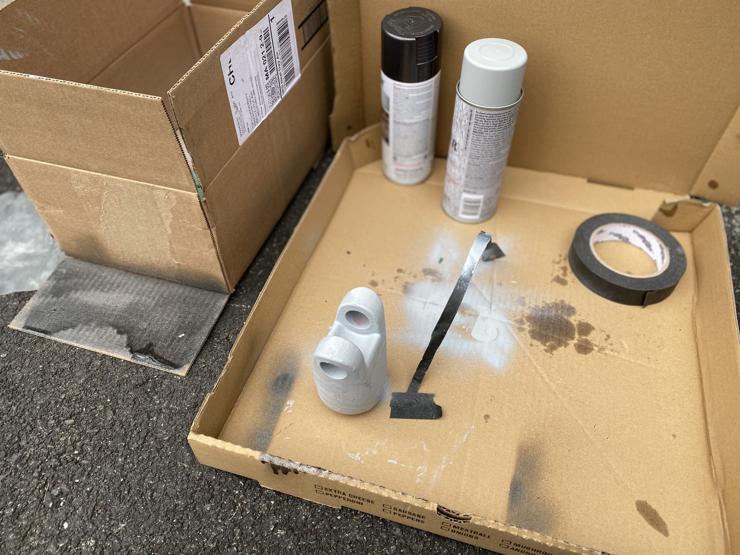
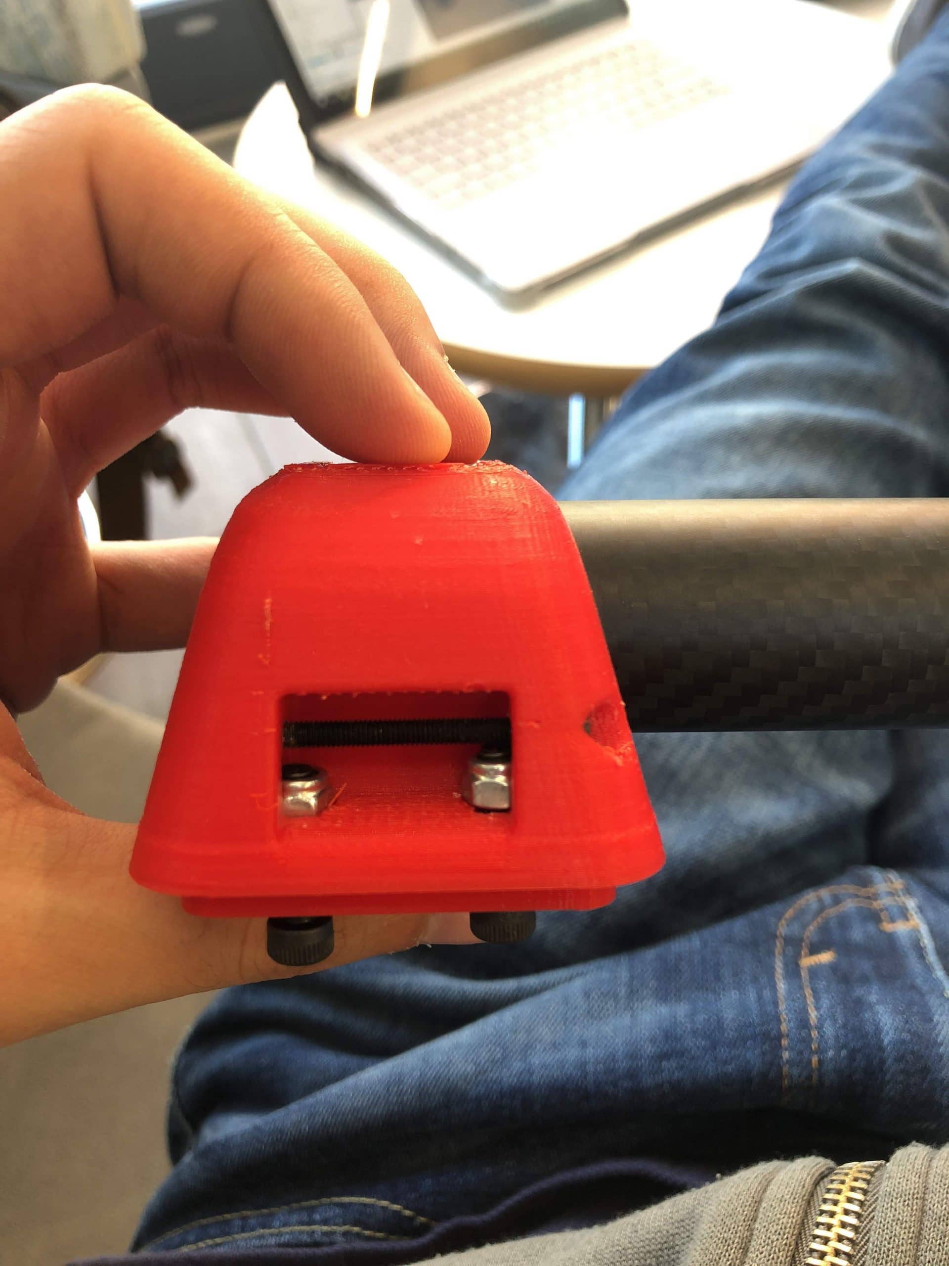
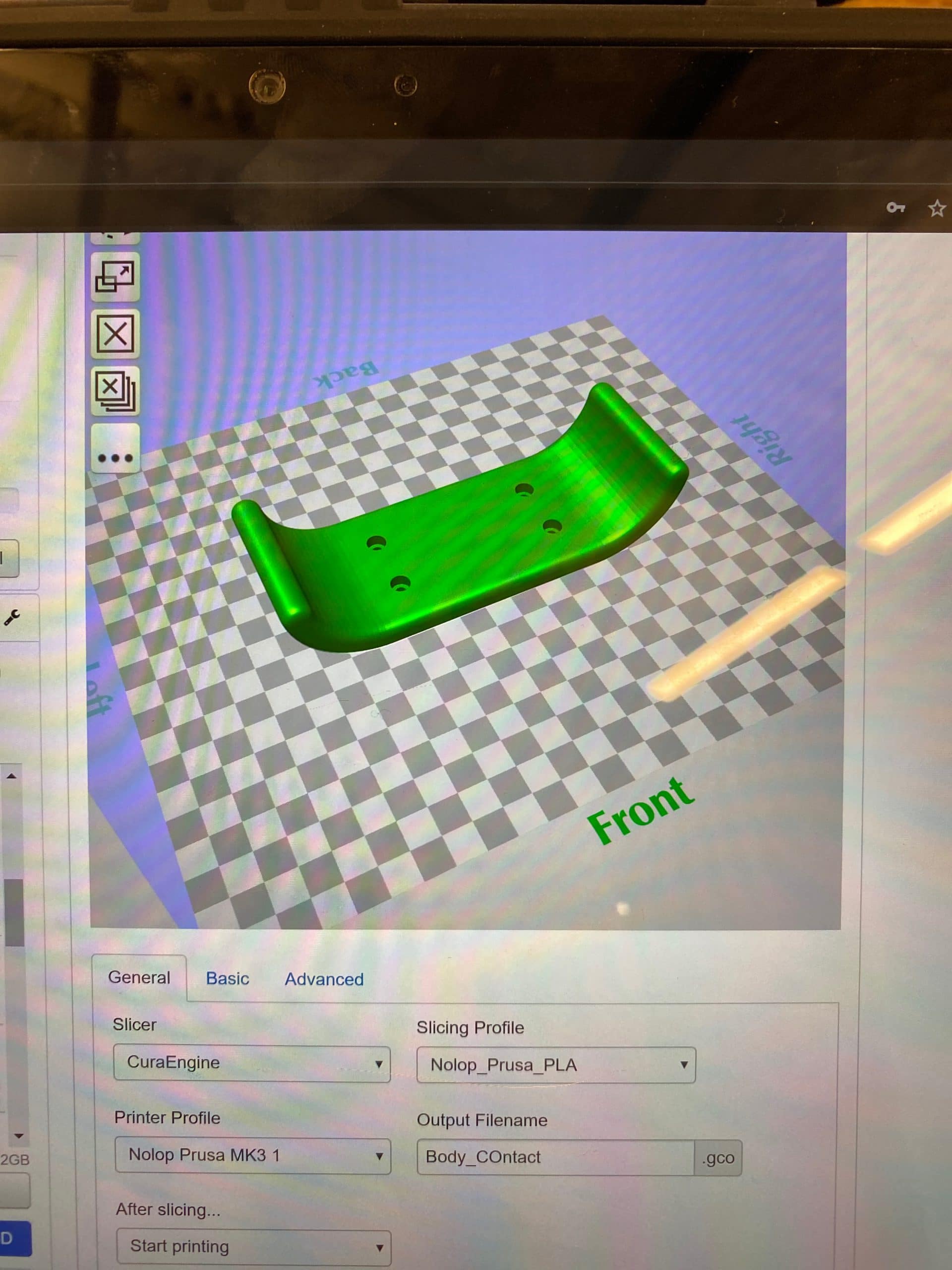
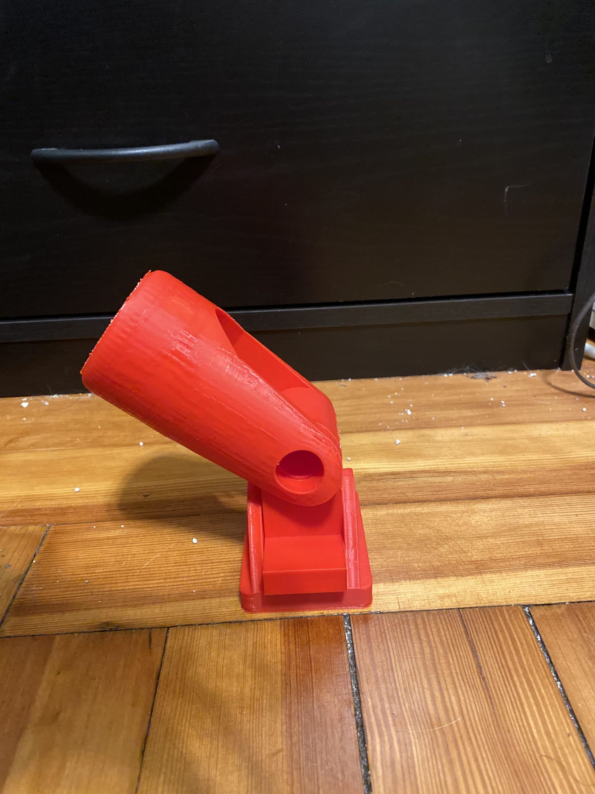
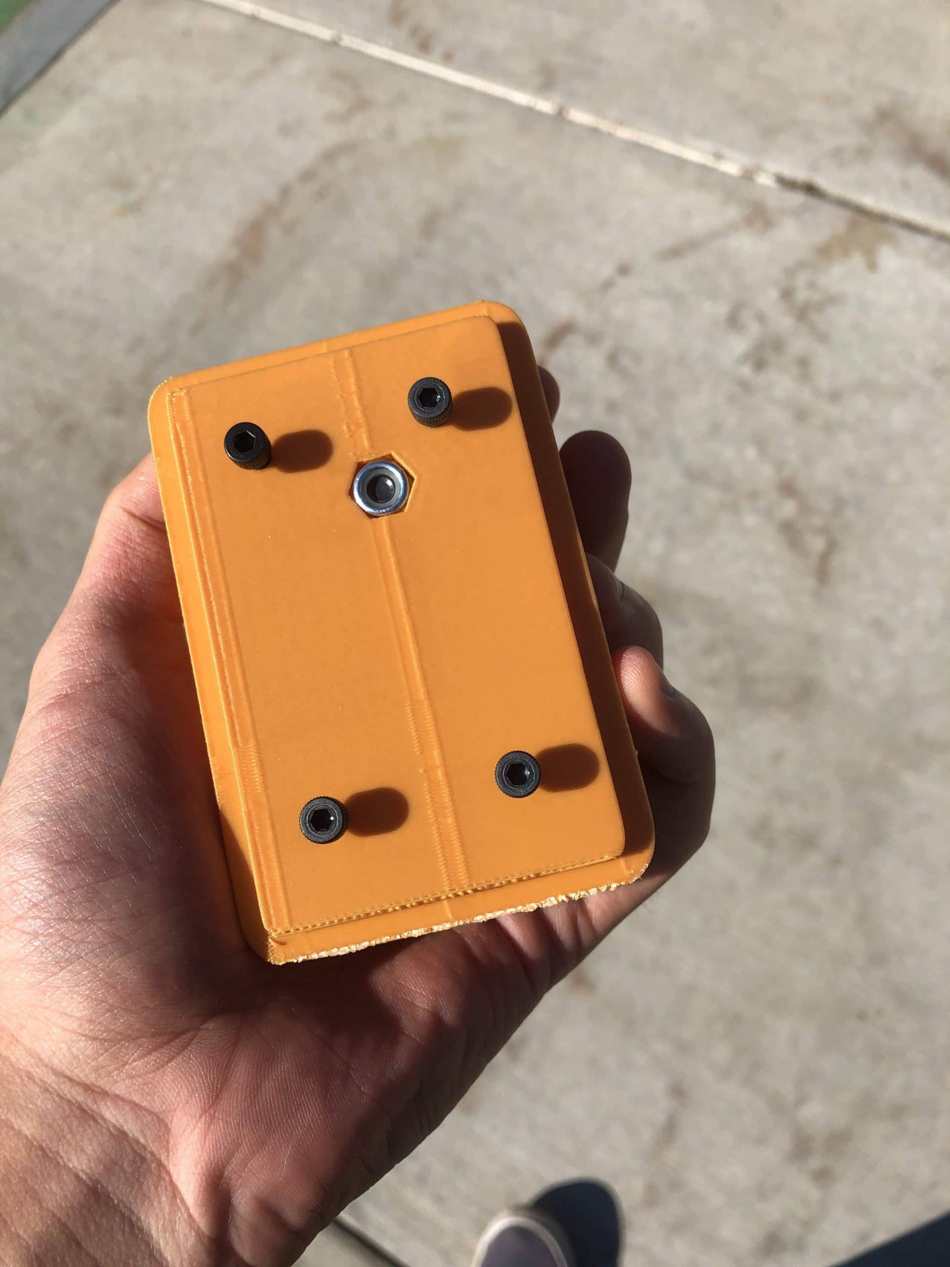
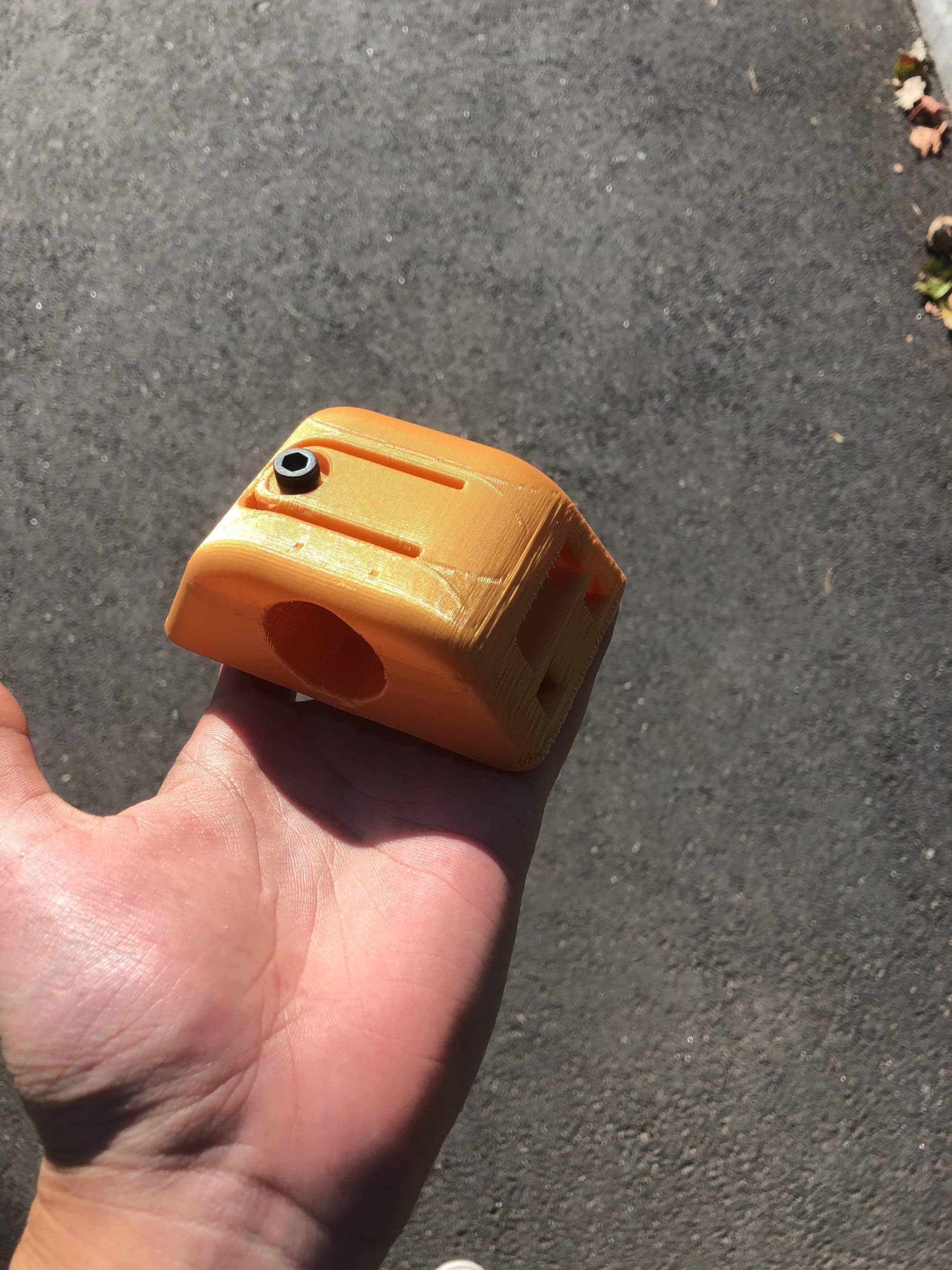
- Version 0 – Fixed Scale + Tolerances
- Unfortunately, two prints totaling 7.5 hrs were produced and immediately destroyed (once by the insertion of the tube and the other time by the attempt to tightening the locking cantilever). Both prints were configured for 20% Fill, 0.5mm Shell, 0.1mm Layers, 65mm/s extrusion rate, and 0.5 mm Top/Bottom. A third print, with slightly enlarged tube ID, was configured (30% Fill, 1mm Shell, 0.1mm Layers, 35mm/s extrusion rate, and 1 mm Top/Bottom) and completed successfully. These settings were used to produce three additional parts.
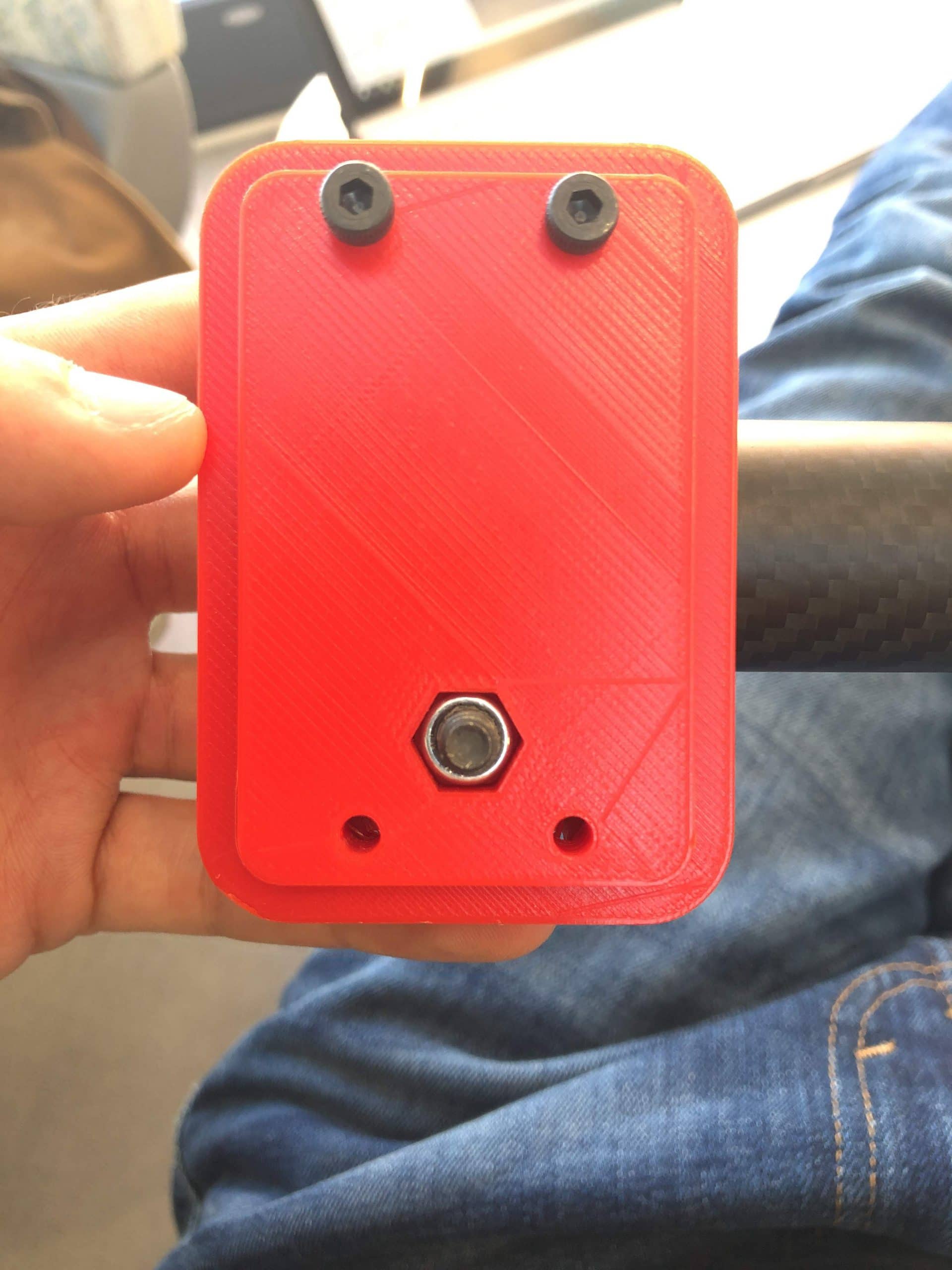
- I felt dissatisfied with the original version because it was too large, had too many complicated \”holes\” in the surface, and cracked due to printing tolerance and tube diameter. I consolidated features and revised the part to consolidate features and reduce the overall footprint:
- Version 0 – Fixed Scale + Tolerances
Design Developments
- 1.0mm cylindrical ribs to secure carbon fiber tubes
- Gearbox Output separated into acrylic and PLA components
Electrical Developments
- Rotary encoder position on PCB corrected.
- oDrive startup protocol configured.
Manufacturing Developments
- Laser Cut 5.5mm Cast Acrylic Gearbox
- Laser Cut 12.80mm Cast Acrylic Gearbox
- FDM 3D printed housing
- SLA 3D printed CAM shaft
Design Developments
- Replacing output gear ring with 37 independent pins and rollers.
- Replaced output bearings with brass bushings.
- Preliminary material selections.
Manufacturing Developments
-
- Submitted 2D and 3D CAD to Machinists
- Design For Manufacturing Complete
- 7075-T6 Aluminum Anodized Exterior
- S45C (AISI 1045) Steel Gear
- Brass Bushings
")
")


Concept – Title
- Young’s Modulus and Ultimate Strength Measured!
- Vertical Buckling Failure – Euler’s Column Formula
- Horizontal Cantilever Failure – Cantilever End Load
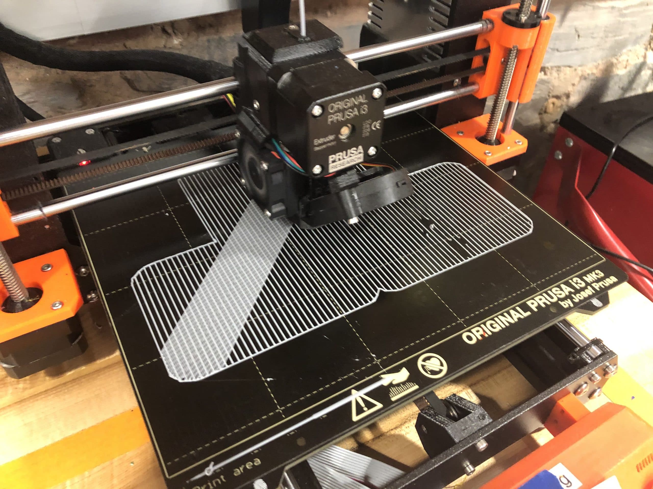
- 1st 3D concept.
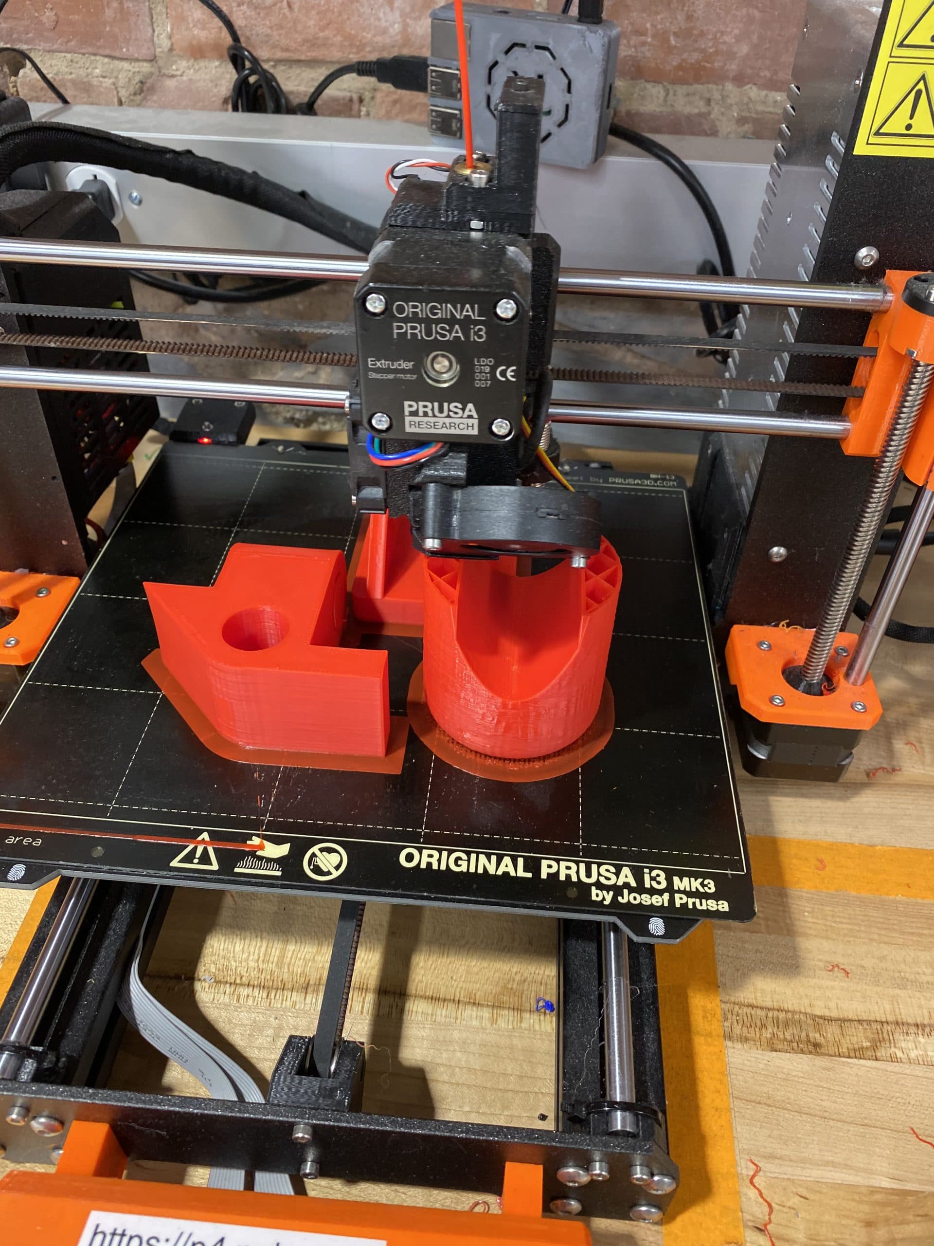
- I prototyped this version at original scale on a Prusa i3 several times. The first attempt resulted in a failed print due to the lack of support scaffolds for unsupported (overhanging) features (printed in grey plastic). In the follow-up print where this problem was addressed, I discovered that a number of dimensions were significantly skewed (more than I would expect from natural part shrinkage). A quick glance at the printer default settings revealed the problem: 20% Fill, 1mm Shell, 0.1mm Layers, 35mm/s extrusion rate, and 0.8 mm Top/Bottom.
- Concept – 1st 3D print
- Started around a cantilever style clamp
- Deflection calculations were not representative of 20% infil prototype
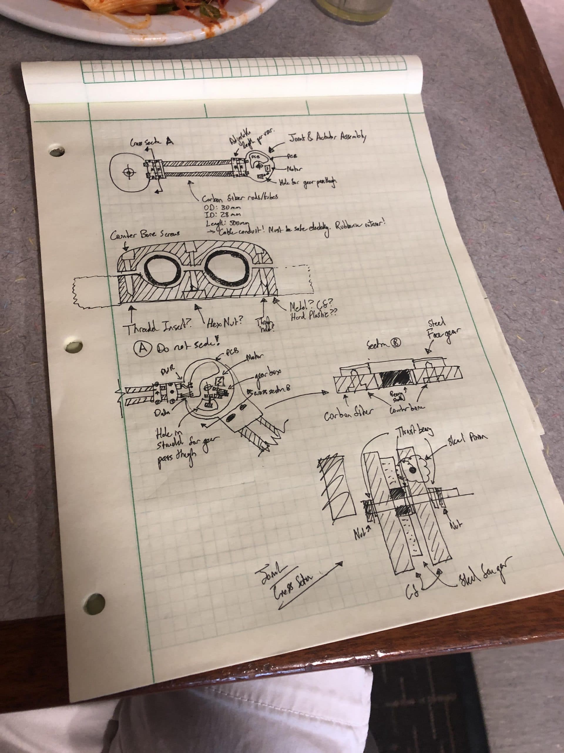
- I am inspired by my meeting with ME professors to develop a basic model or frame that I can develop simultaneously alongside my control system. Concept art helps me organize and visual critical functions and features that the frame and actuator system shall include. Furthermore, I will be able to test my system at an earlier date if the frame is simultaneously developed and identify unforeseen complications and bugs. I have thrown together a sketch which I plan to convert to a CAD model later tonight.
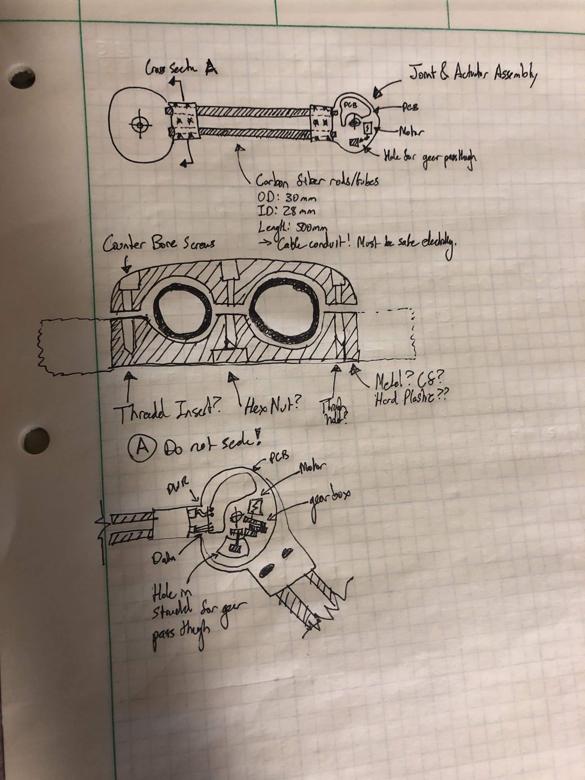
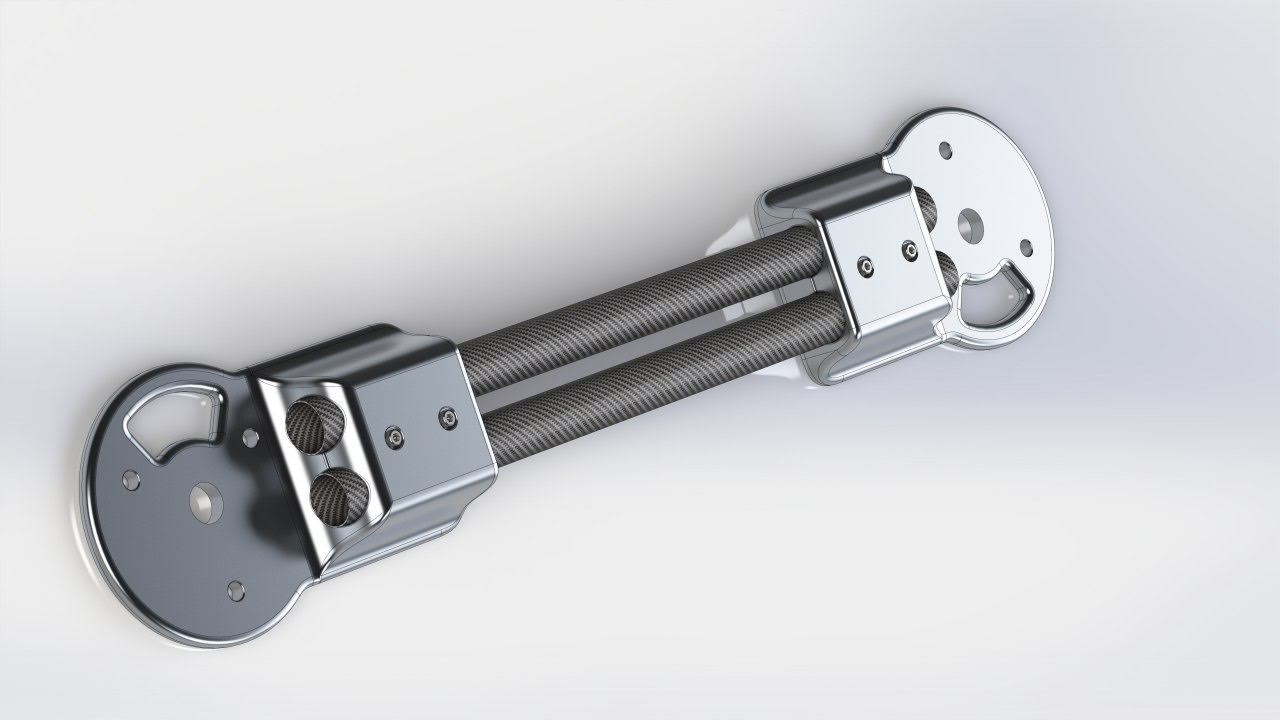
- Based on drawings from lunch, I executed a basic CAD model that incorporates the features I considered noteworthy. Because this is a draft and model ONLY the following considerations should be noted:
- Manufacture of the “joints” by 3D printing, rendered as CNC 6061-T6.\r\nStronger as a single part with two screws than two parts with six screws. Did not separate the “pinch” clamping of the tubes – review later when more data is available.
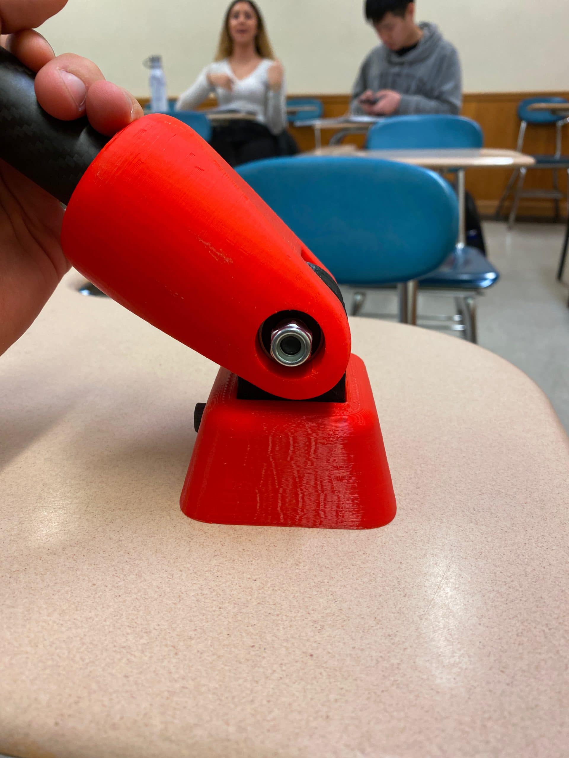
- Counter bore ANSI Metric M5 with Washer\r\nANSI metric M5 nut on backside rather than threading on part (because that’ll strip out easy) or insert (because it fatigues the material)
- SKF 608 series bearing. Cheap, easy, and common. I have abused these and they’re fine under absurd loads and speeds that could never apply to this joint. Note that thrust bearings will be needed when gears are attached
- Three mounting holes for a face gear.
- Window for pinion access to face gear.
- Gearbox integration behind the pinion.
- PCB mounting points undefined – unlikely I will have a PCB version before I 3D print and test assembly this for the first time.
- Bottom of the parts are labeled with date, version, name, etc.
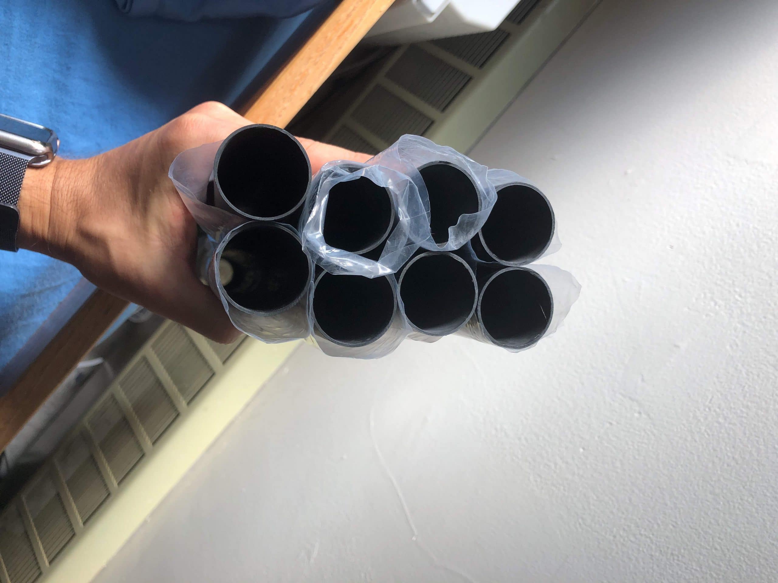
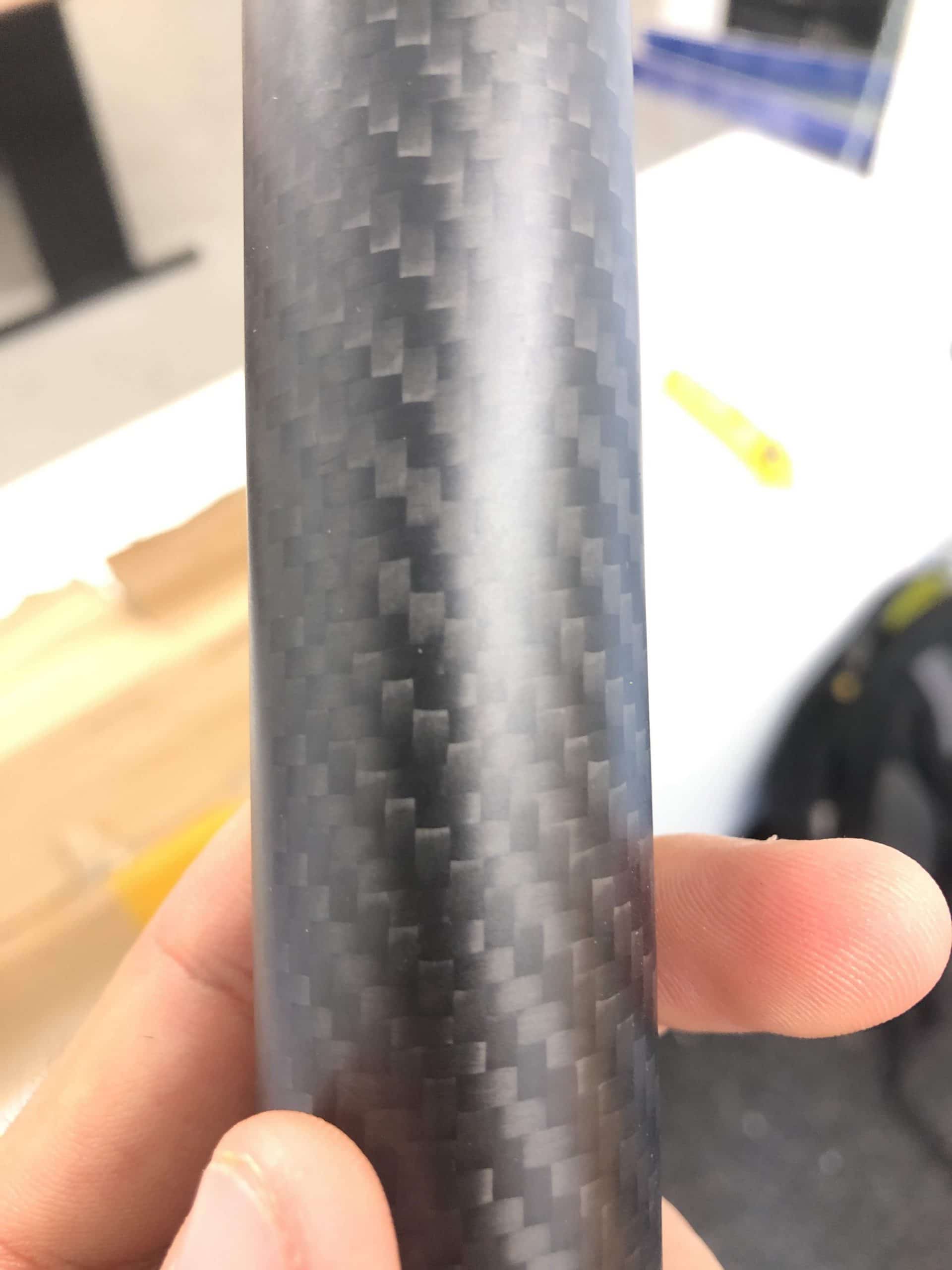
- Carbon fiber tube is 1.5x stronger than aluminum equivalent part and lighter. Need to meet with professor Zimmerman to evaluate broader use of composites.
- IF back emf cannot be used for accurate position estimation, then use a Hall effect sensor + encoder ring machined into face gear to provide angular position.
- Concept – what if I spec DC motors 28mm OD to fit INSIDE the CF tubes. What if I also draw my PCB to fit inside the tubes? Natural RF blocking by the CF and it makes the assembly easier to seal and waterproof.
- Velcro and Neoprene Straps
Design Developments
- 1.0mm cylindrical ribs to secure carbon fiber tubes
- Gearbox Output separated into acrylic and PLA components
Electrical Developments
- Rotary encoder position on PCB corrected.
- oDrive startup protocol configured.
Manufacturing Developments
- Laser Cut 5.5mm Cast Acrylic Gearbox
- Laser Cut 12.80mm Cast Acrylic Gearbox
- FDM 3D printed housing
- SLA 3D printed CAM shaft
Design Developments
- Replacing output gear ring with 37 independent pins and rollers.
- Replaced output bearings with brass bushings.
- Preliminary material selections.
Manufacturing Developments
-
- Submitted 2D and 3D CAD to Machinists
- Design For Manufacturing Complete
- 7075-T6 Aluminum Anodized Exterior
- S45C (AISI 1045) Steel Gear
- Brass Bushings
")
")

")
")

