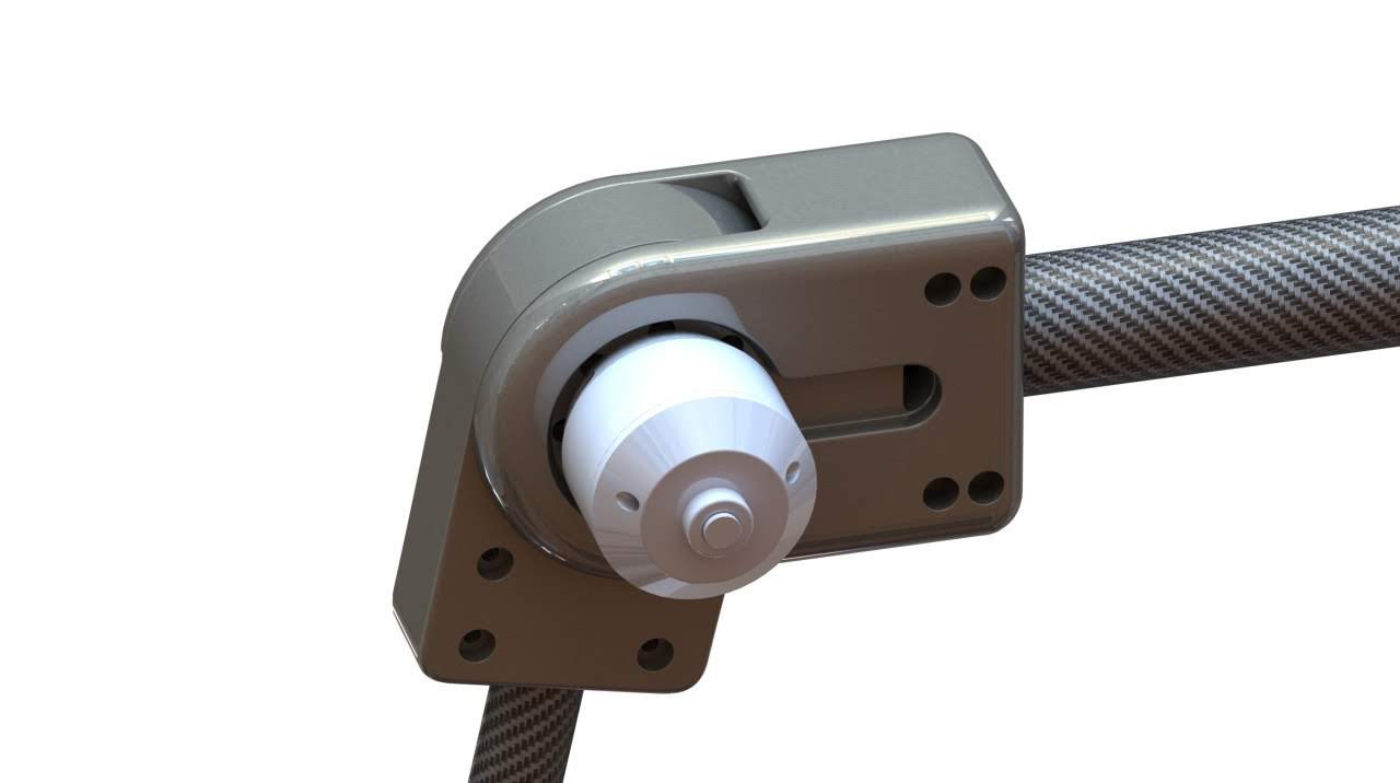
StryDrive™ is an actuator built into the joint of the Strydr Exoskeleton. An actuator converts energy into motion that moves or controls a mechanism or system. It can introduce motion as well as prevent it. StryDrive™ uses a brushless DC motor to convert electricity into torque which is amplified by a gearbox to produce or prevent motion at the joint.
Revision History
Scroll down to learn about the process
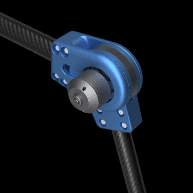
Revision 6 – StryDrive™ Generation 1
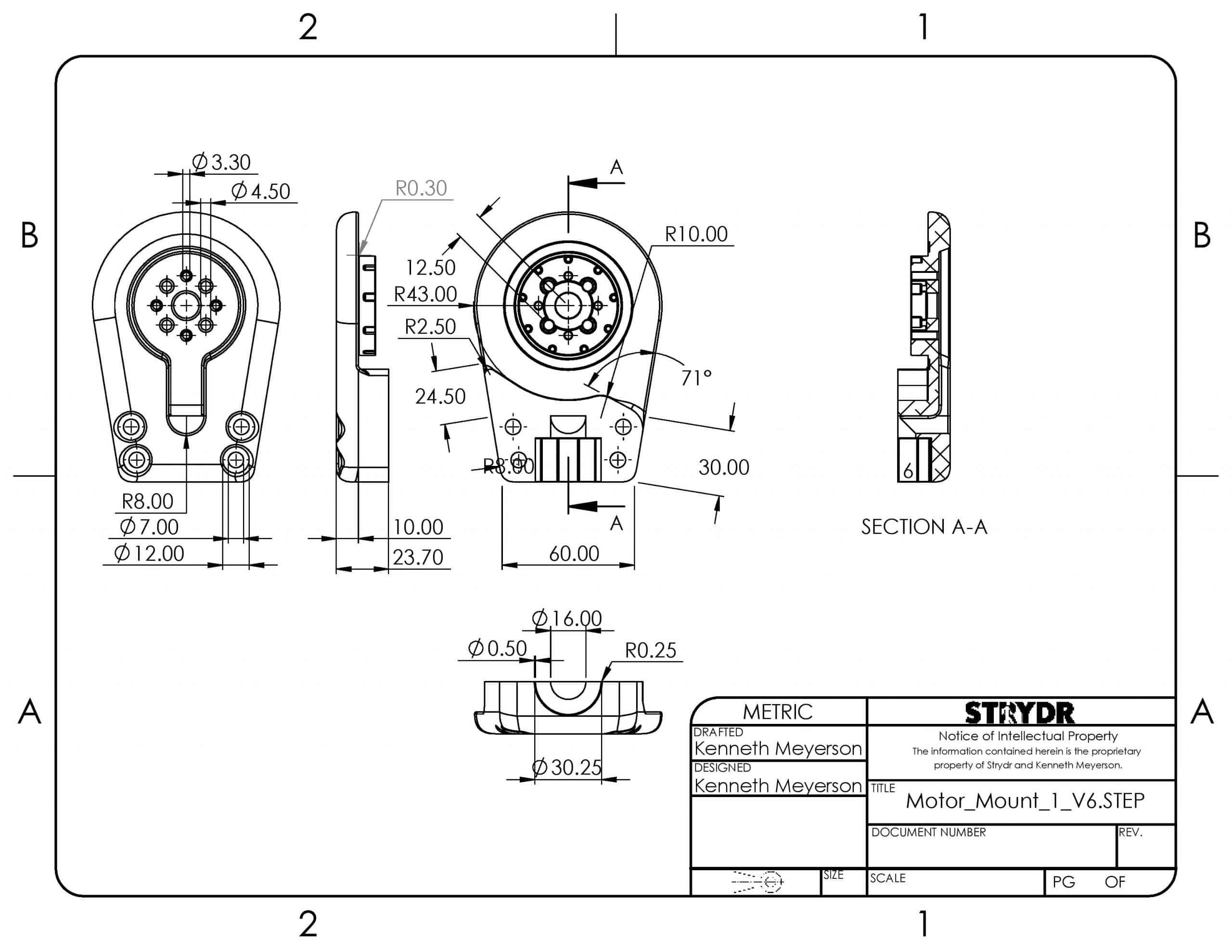
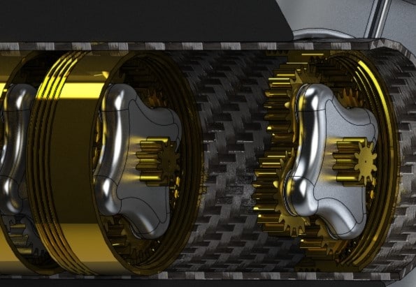
Revision 6 of the StryDrive™ gearbox is an adaptation of the Revision 5 gearbox designed for easy CNC mental fabrication. This transition reduces the probability of prototype defects due associated material strength and deformation limitations of plastic 3D printing and acrylic laser cutting. Although the 3D printed and laser cut designs can be produced with 3-axis CNC milling, the assembly relies on self-tapping screws and other incompatible features.
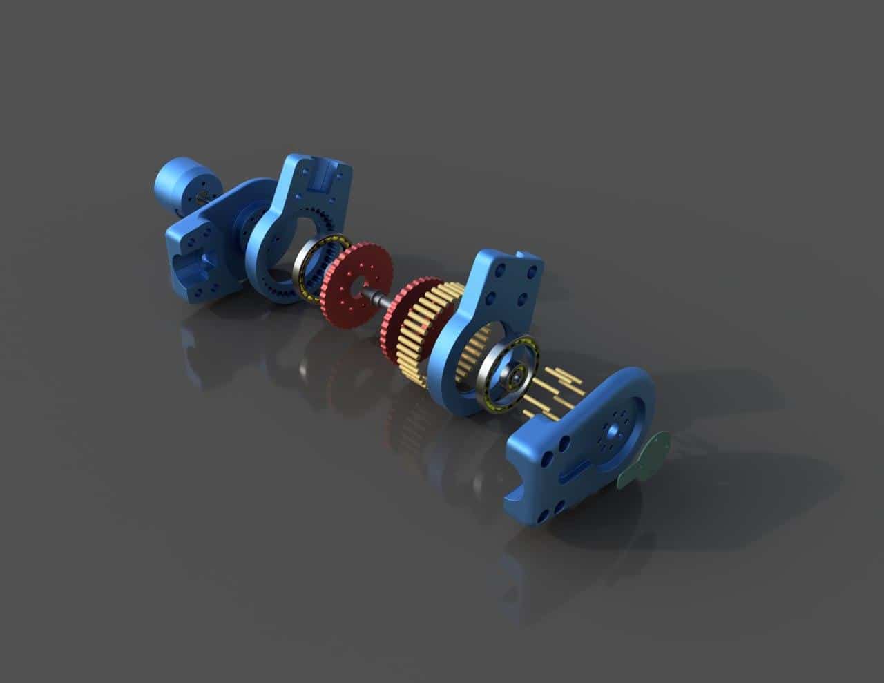
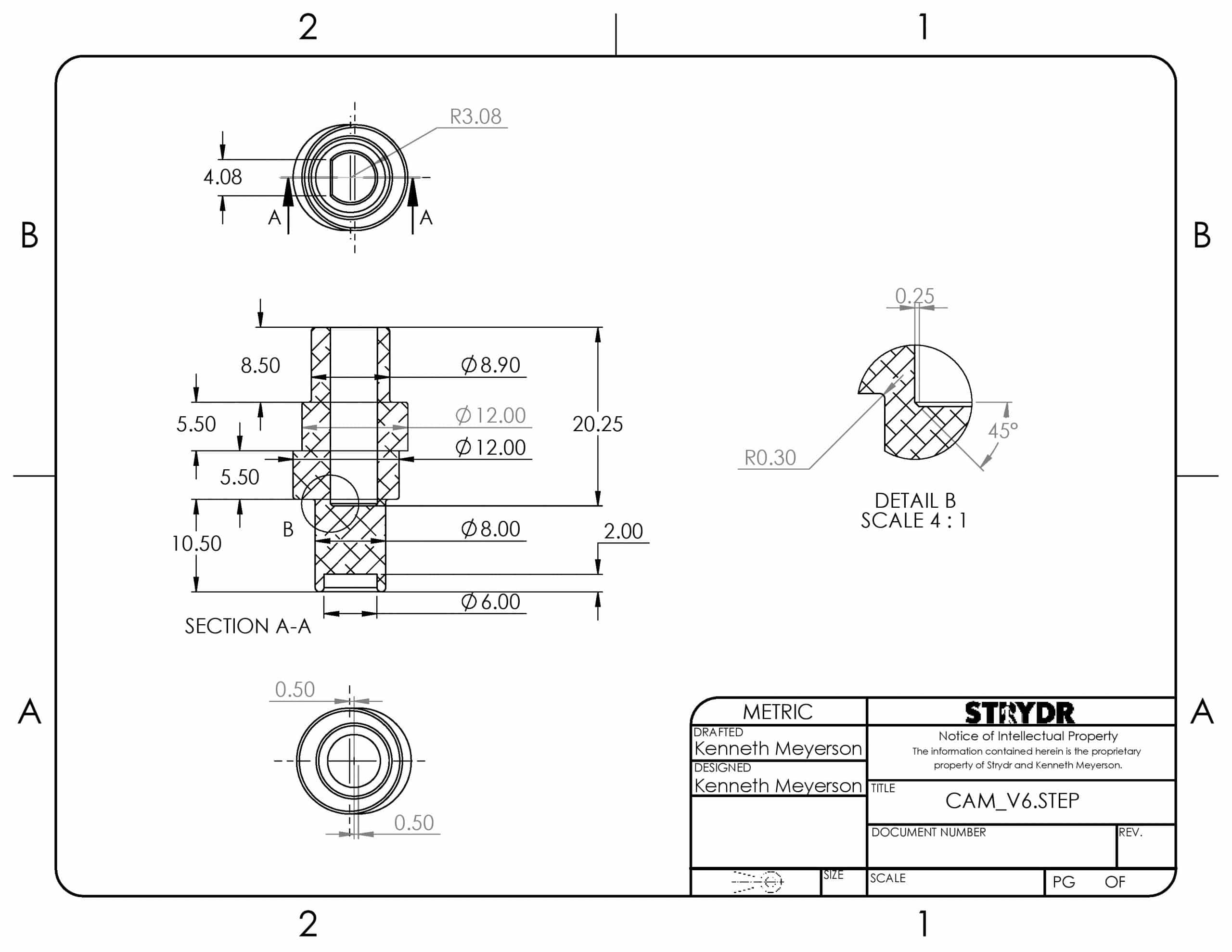
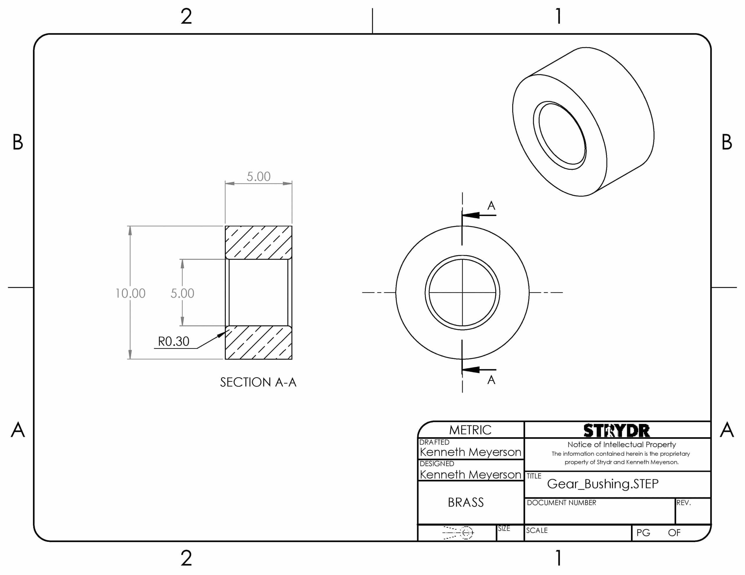
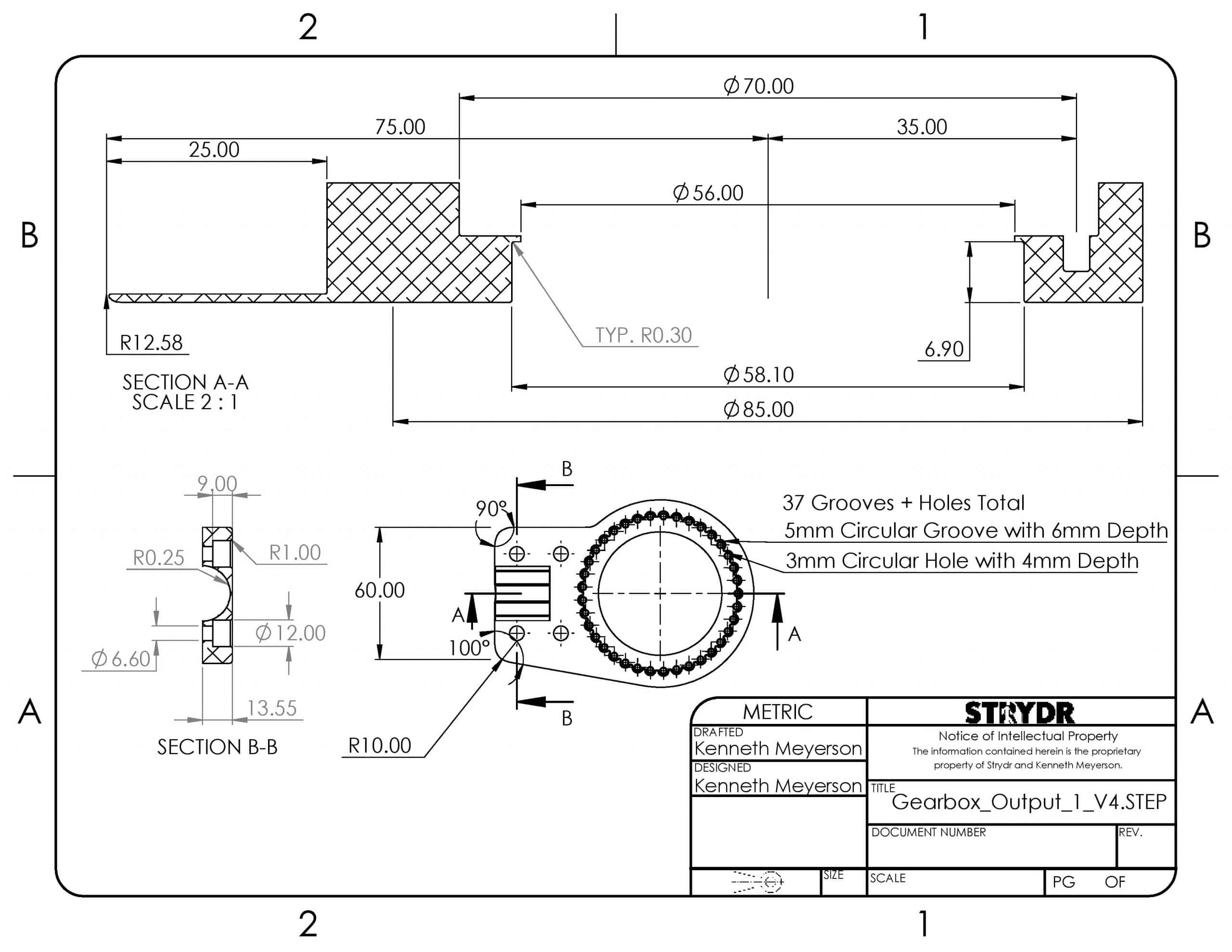
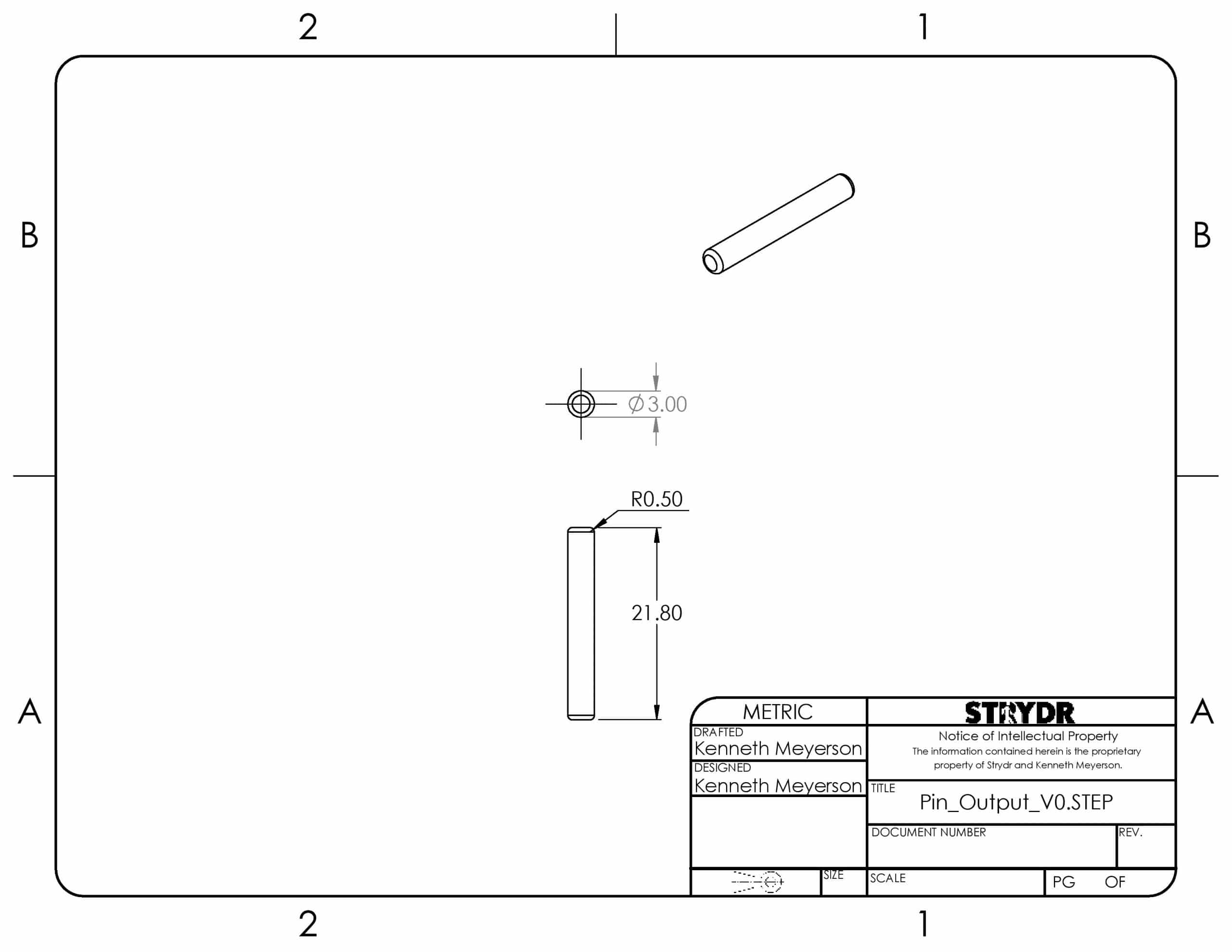
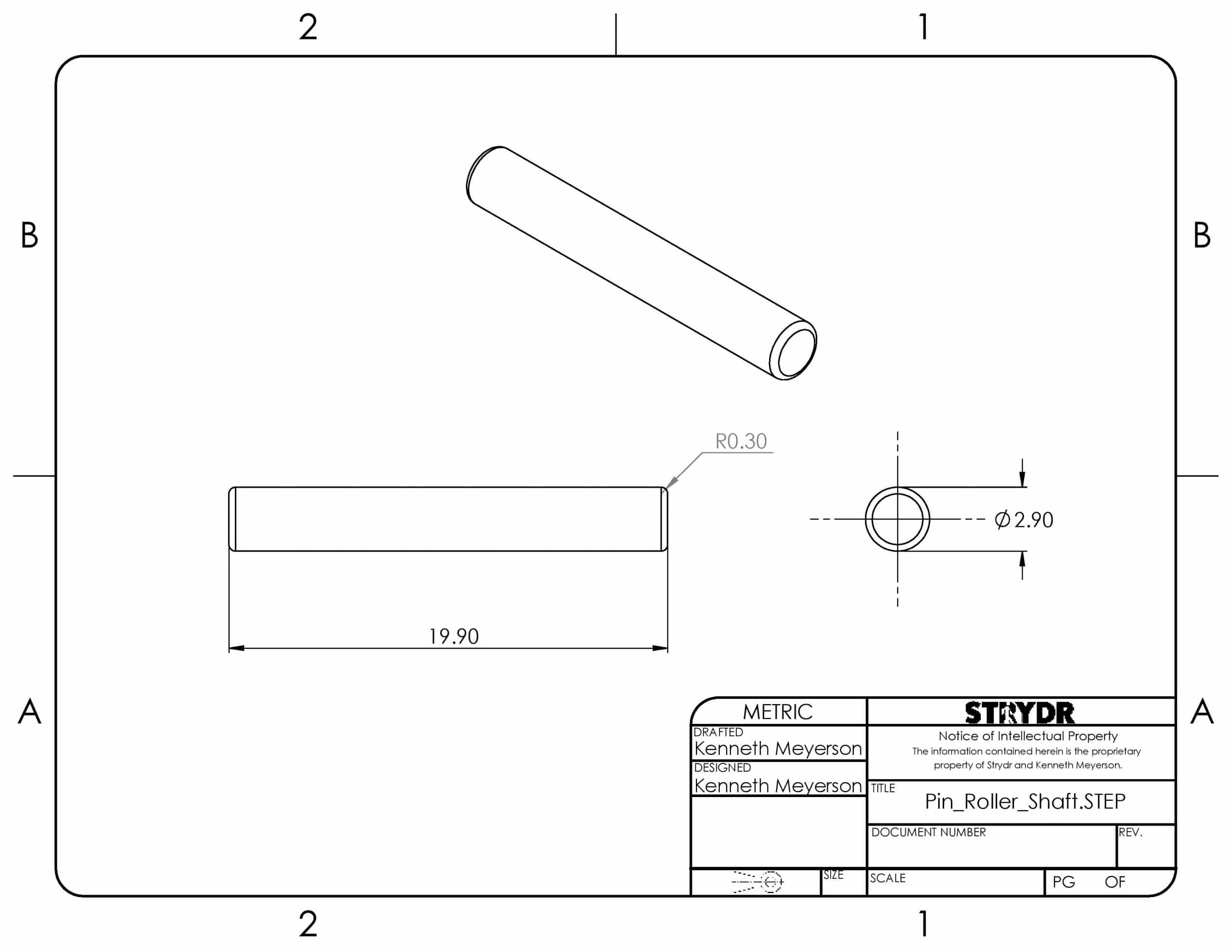
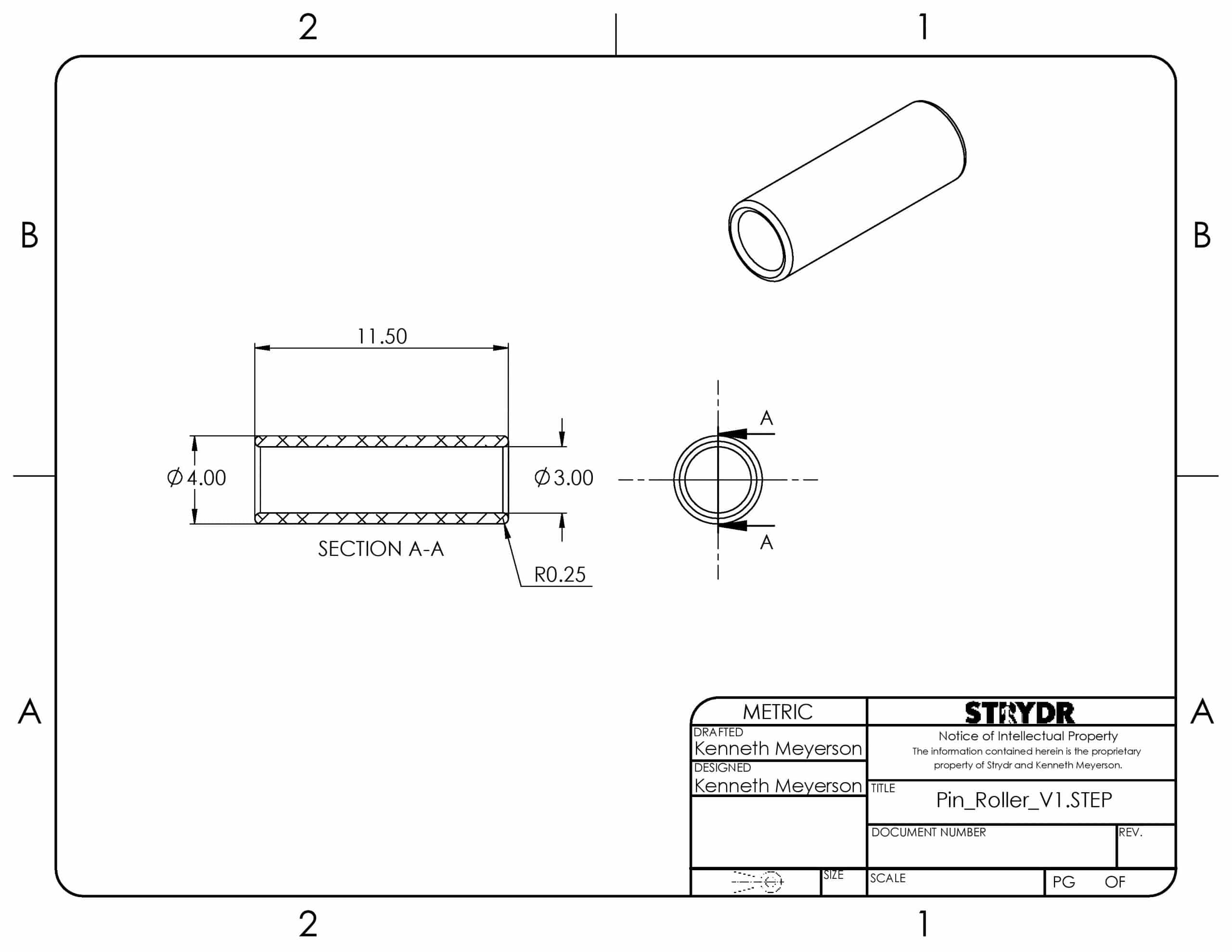
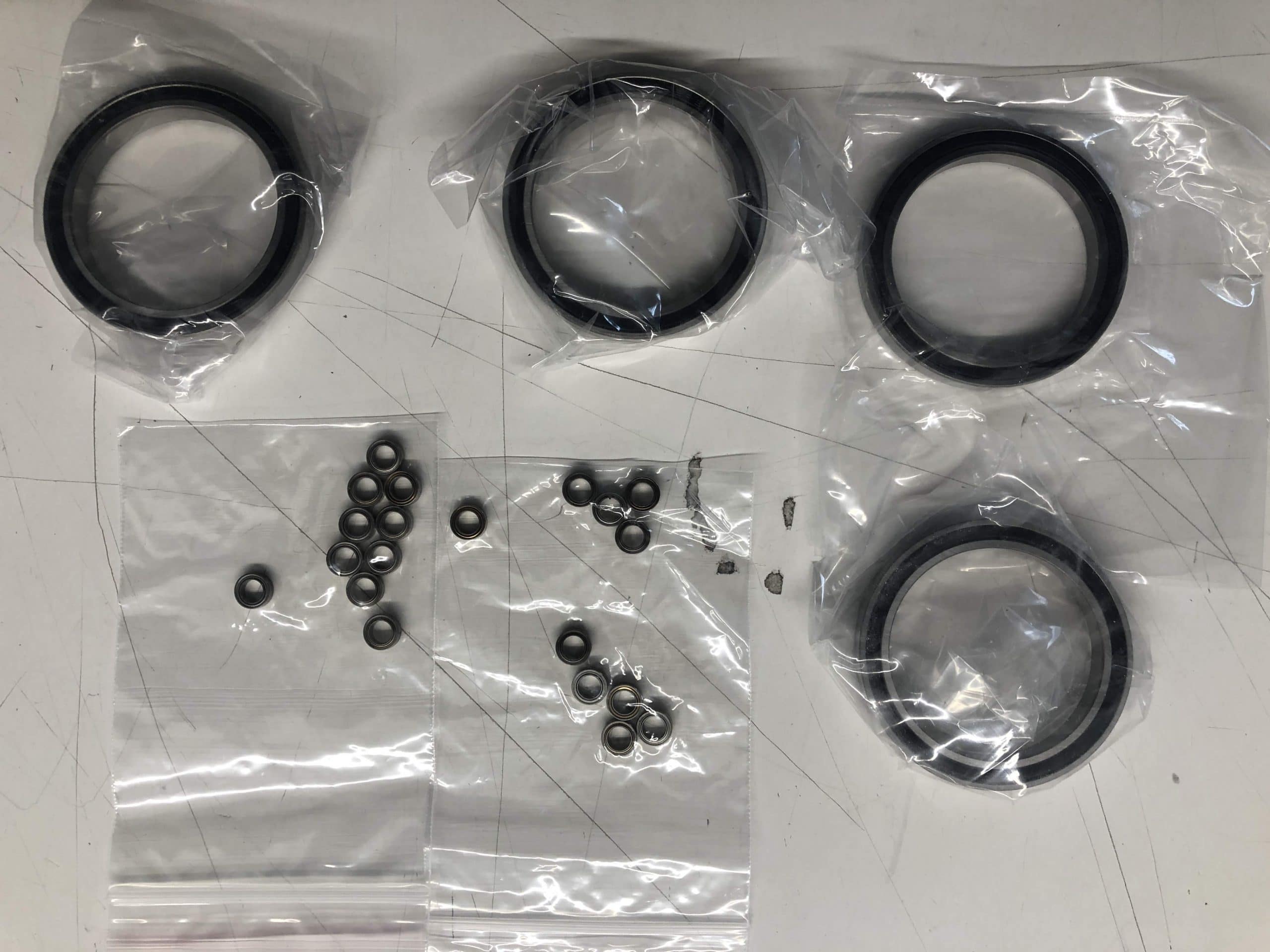
The major change incurred by the adaptation is the replacement of the previously laser cut outer gear rings with 37 independent support pins and rolling sleeves. This change eliminates the sliding friction with rolling friction to minimize fictional losses and maximize silence. Smaller changes replacing the small bearings connecting the gears with the output shaft with brass bushings. This minimizes the BOM cost, simplifies assembly, and improves durability.
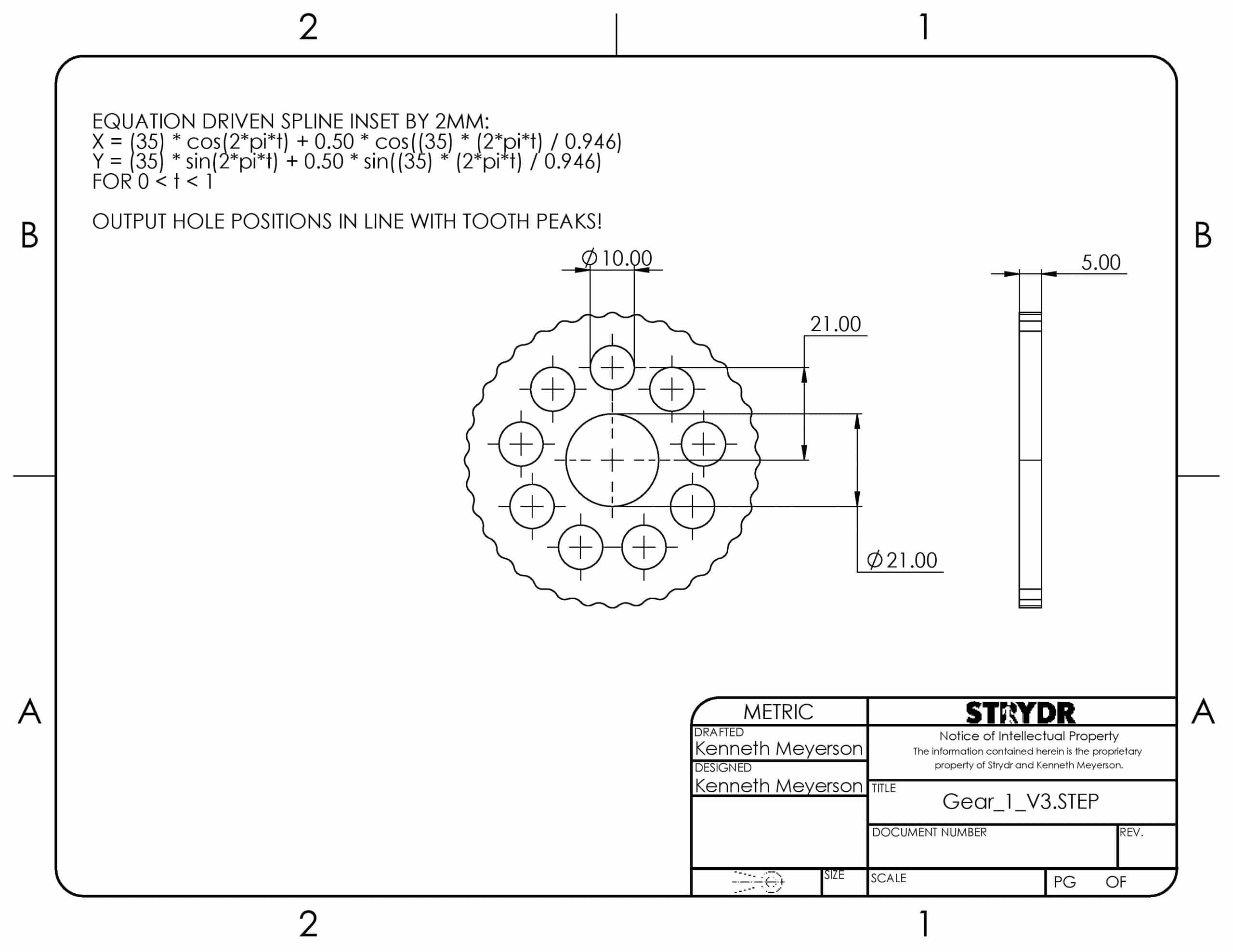
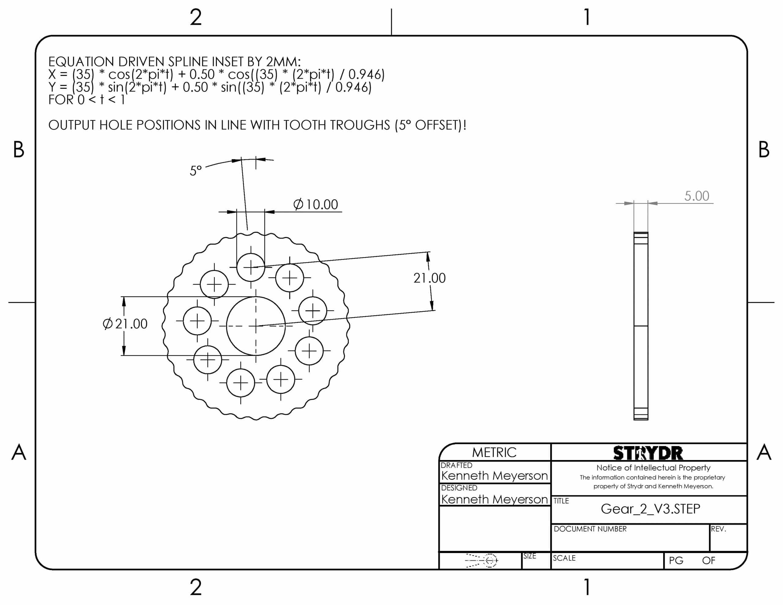
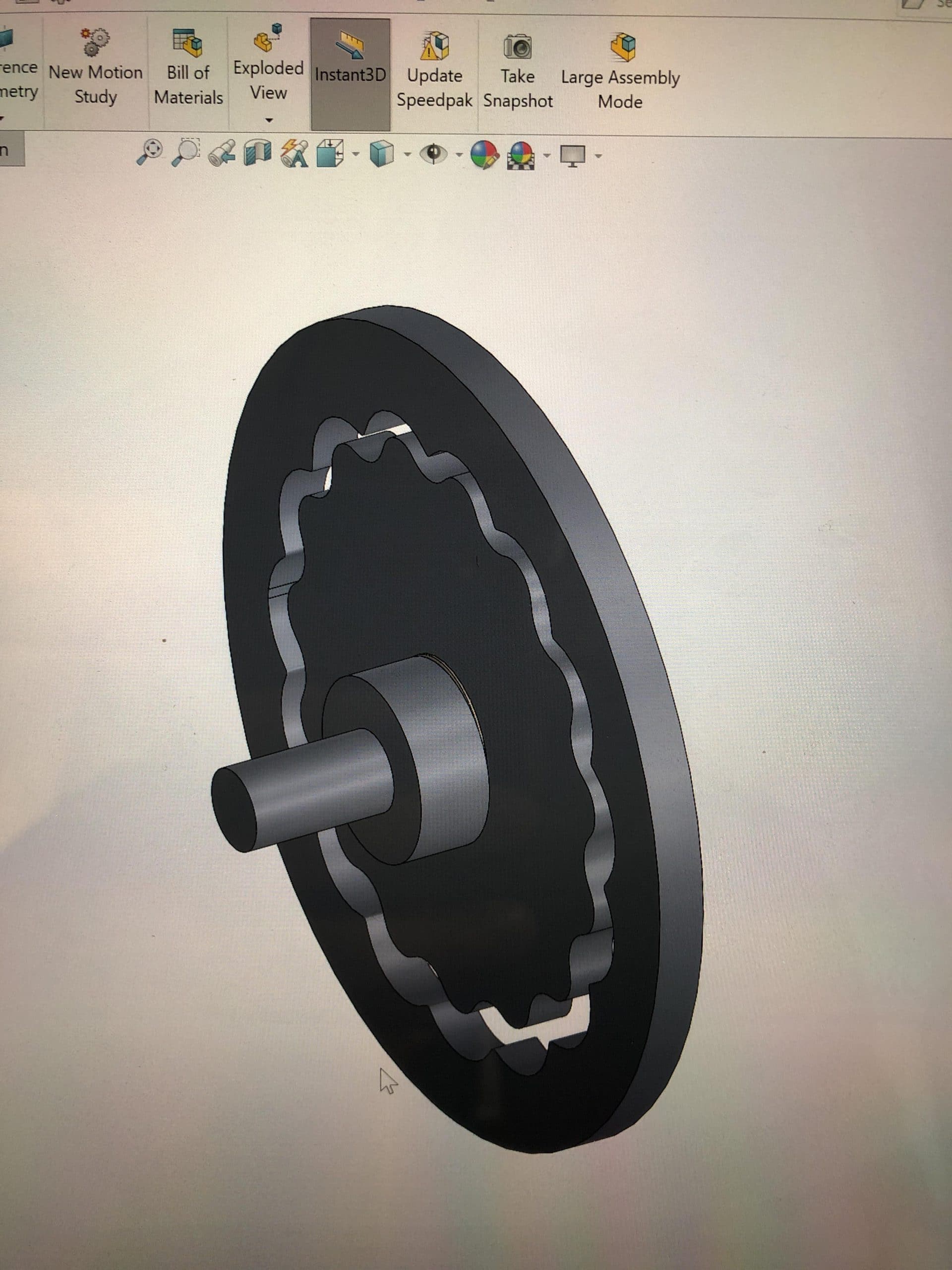
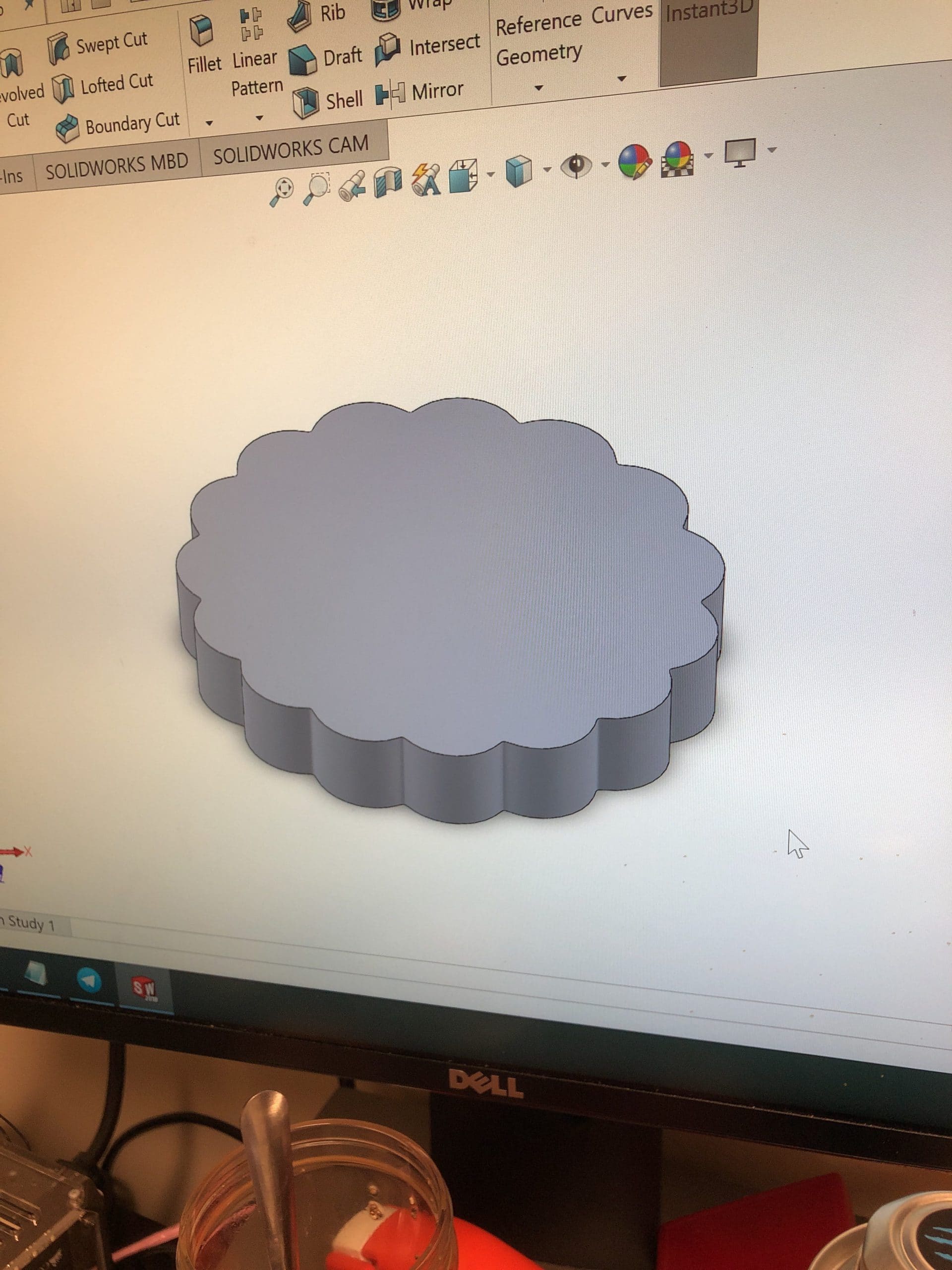
Although Finite Element Analysis (FEA) is typically used to predict the pressures within the gearbox at the high-end torque rating of 100 Nm, Solidworks cannot perform the CAM mate with the gears equation driven splines that compose the gears. I have not found a way to circumvent the error wherein the self-intersection of the spline-curve is treated as a discontinuity rather than as a point of tangency. Forcing tangency or the mate over-defines the sketch or model causing build errors. I estimated material selections with some back of the envelope calculations regarding the expected stresses and associated magnitude of strain.
I consulted my coworkers in China and performed a final DFM study. 7075-T6 aluminum is an inexpensive and lightweight material to prototype the parts with, however it does not exhibit infinite service life. Because I do not have a functional FEA model, the gears will be manufactured from S45C (or AISI 1045 equivalent) to mitigate the possibility of cyclic loading fatigue.
Design Developments
- Replacing output gear ring with 37 independent pins and rollers.
- Replaced output bearings with brass bushings.
- Preliminary material selections.
Manufacturing Developments
-
- Submitted 2D and 3D CAD to Machinists
- Design For Manufacturing Complete
- 7075-T6 Aluminum Anodized Exterior
- S45C (AISI 1045) Steel Gear
- Brass Bushings


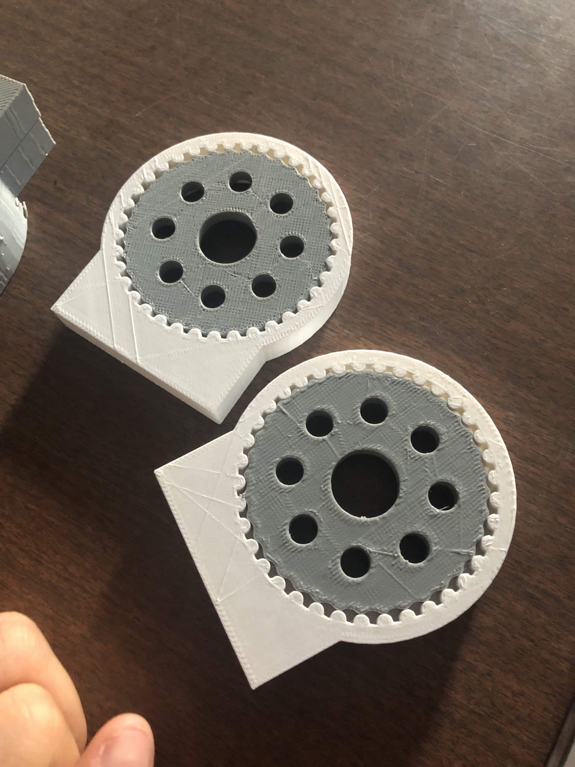
Revision 5 – Complete Drive Assembly
-
Acknowledging limitations of Tufts Manufacturing
- Sensitive to tolerances, worth making out of metal to test if dimensions are workable.
- Switched to Laser Cutting accuracy sensitive parts
- Depth of cut reveals laser is not perpendicular to surface, resulting in CAM shaft misalignment. Discovered when replacing two separate outer gear disks with a single piece.
- Replaced CAM Shaft Material due to breakage
-
Reviewed design of the Cycloidal Gear Geometry
- Increasing eccentricity of CAM will help reduce skipping, required additional changed.
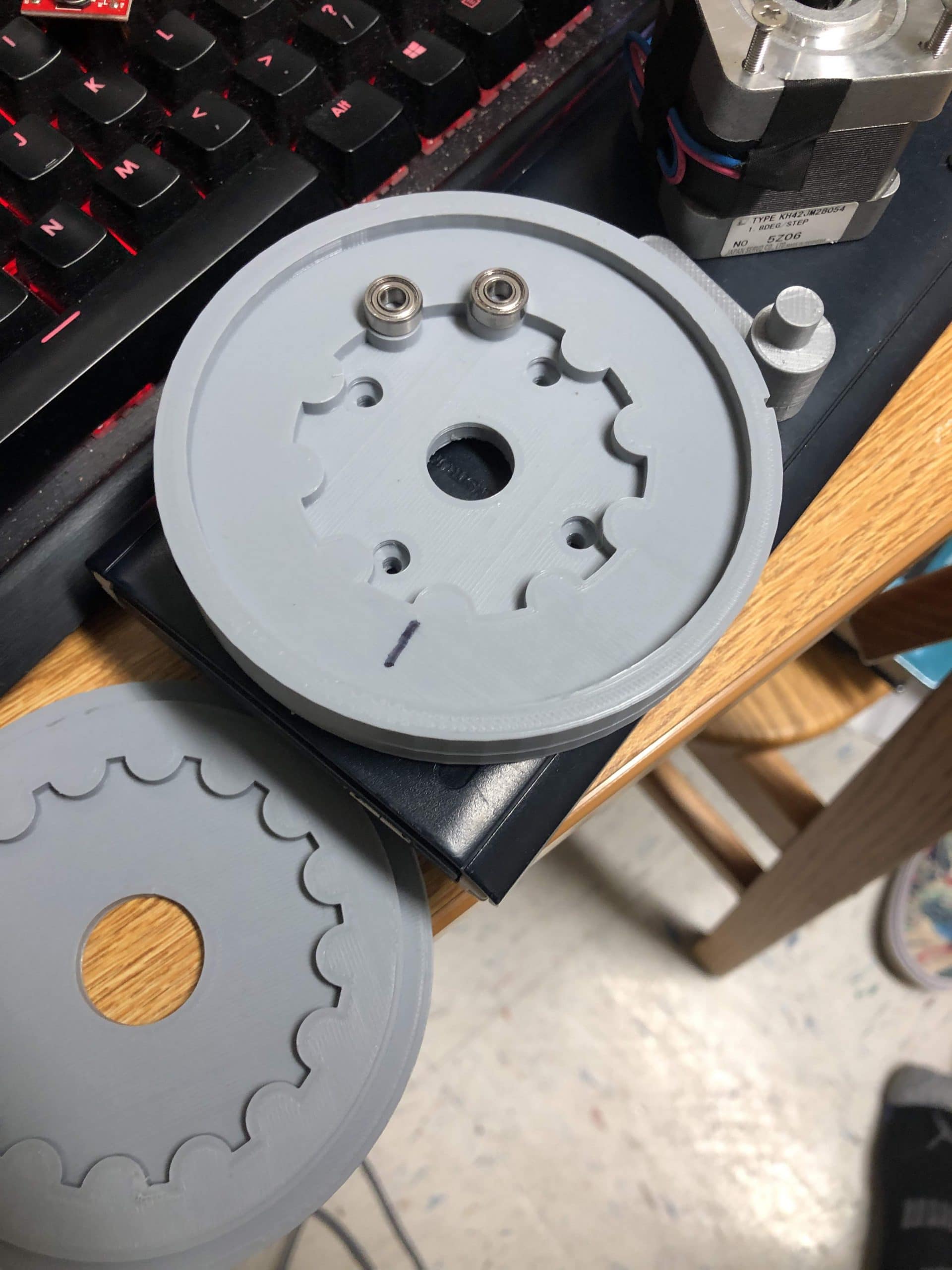
- Placed output holes in line with the peaks or troughs of the gear for Top and bottom. This geometry was not fully constrained previously due to software limitations with equation drive splines.
- It is working a lot better! Time to put a pin in this version of the gearbox!
-
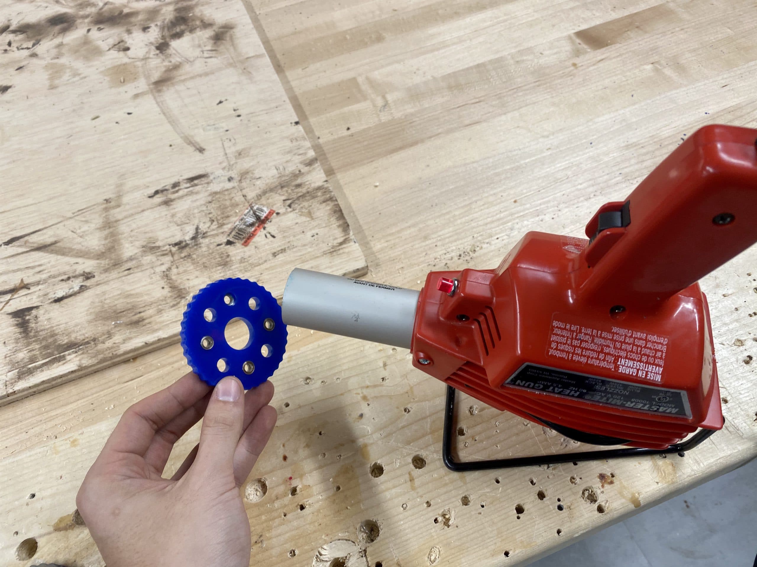
Revised the Carbon Fiber Tube Clamping system
- Ridges to add tension
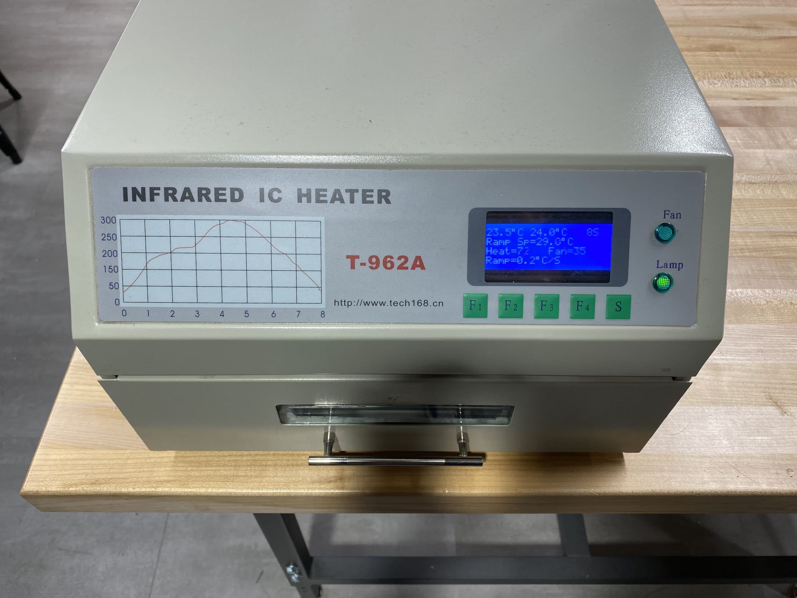
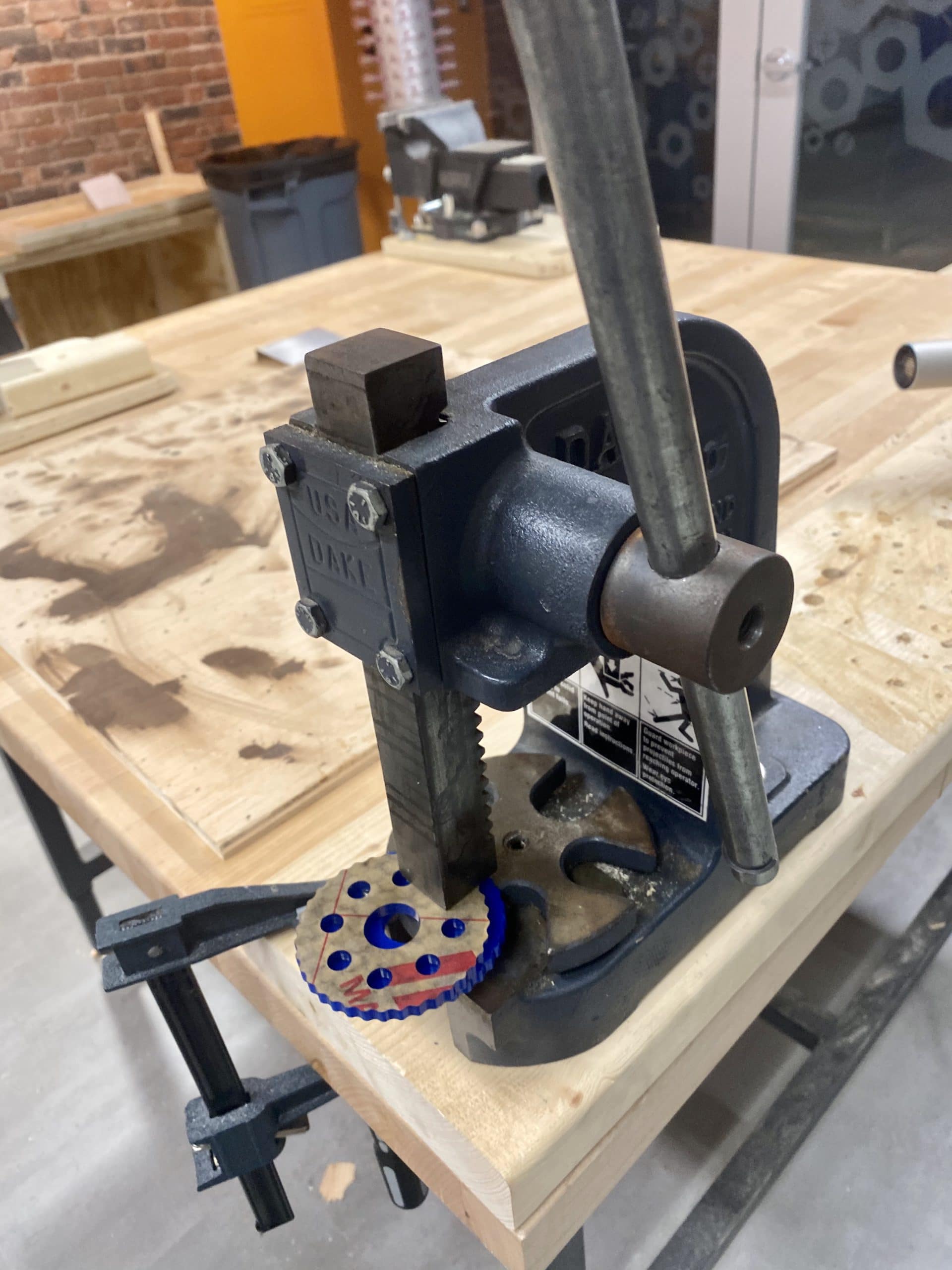
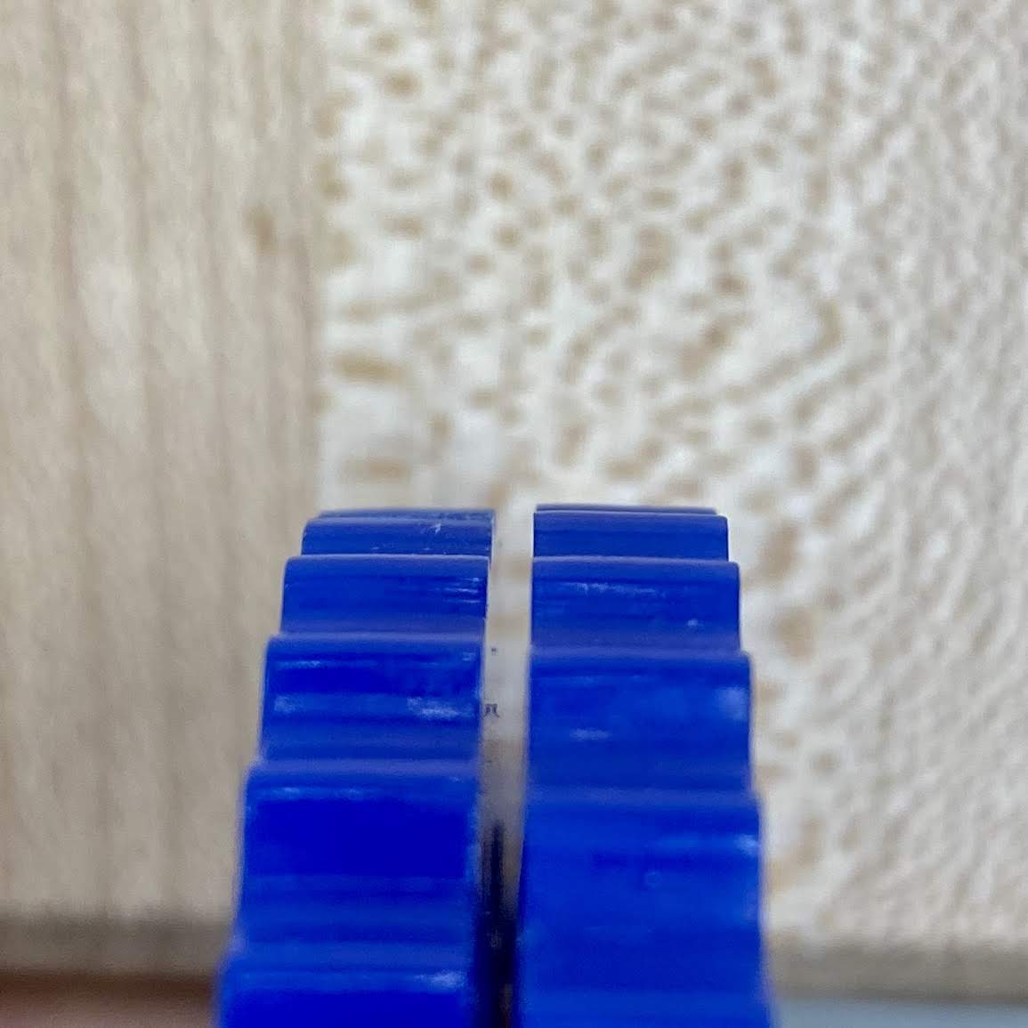
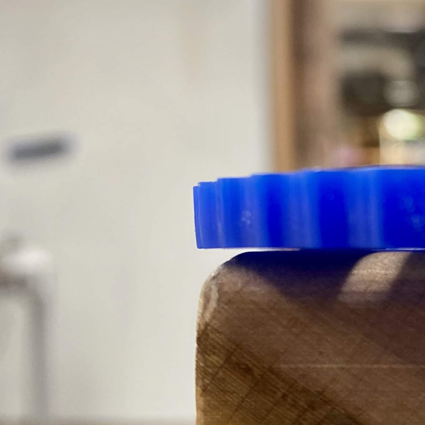
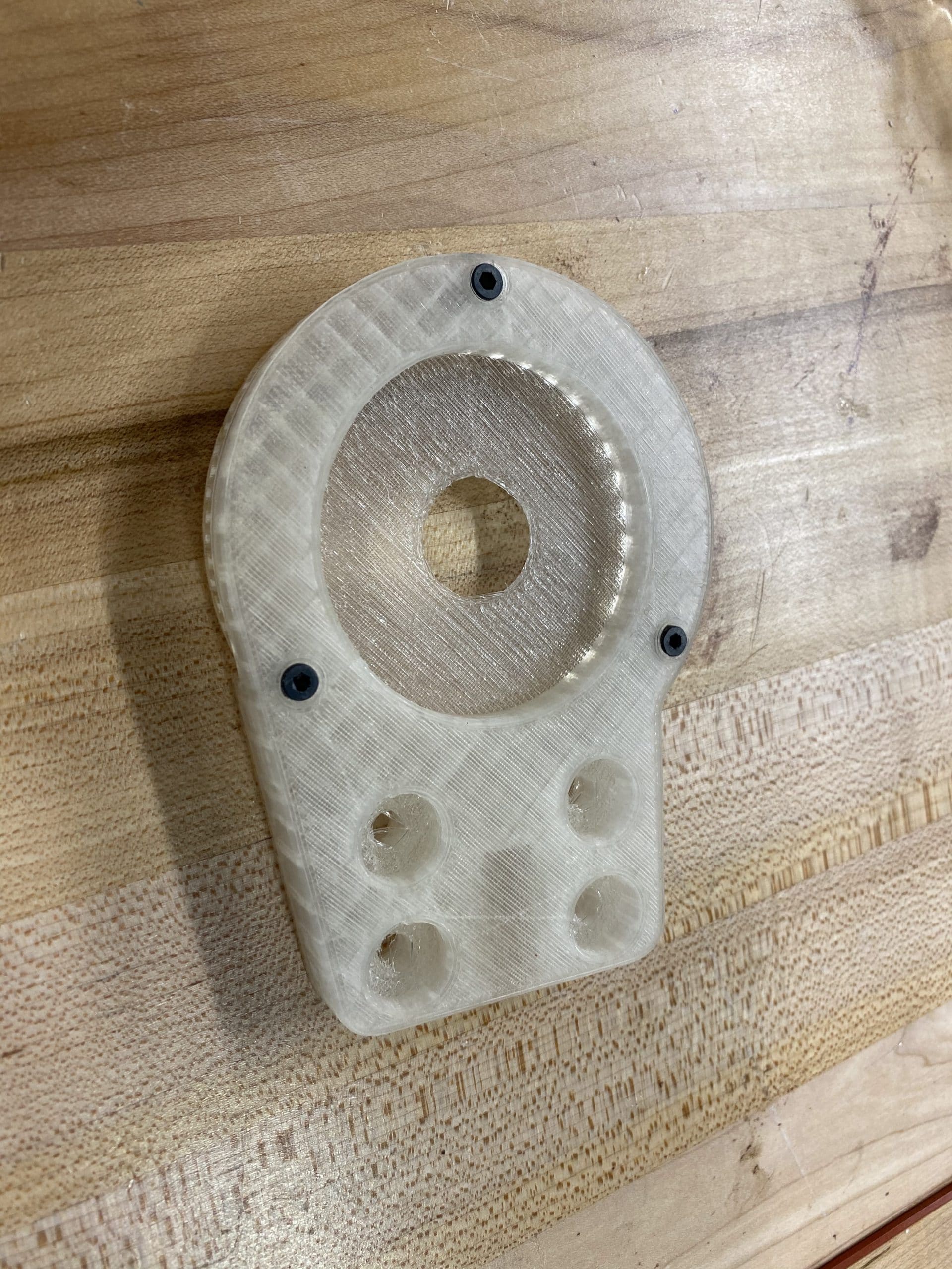
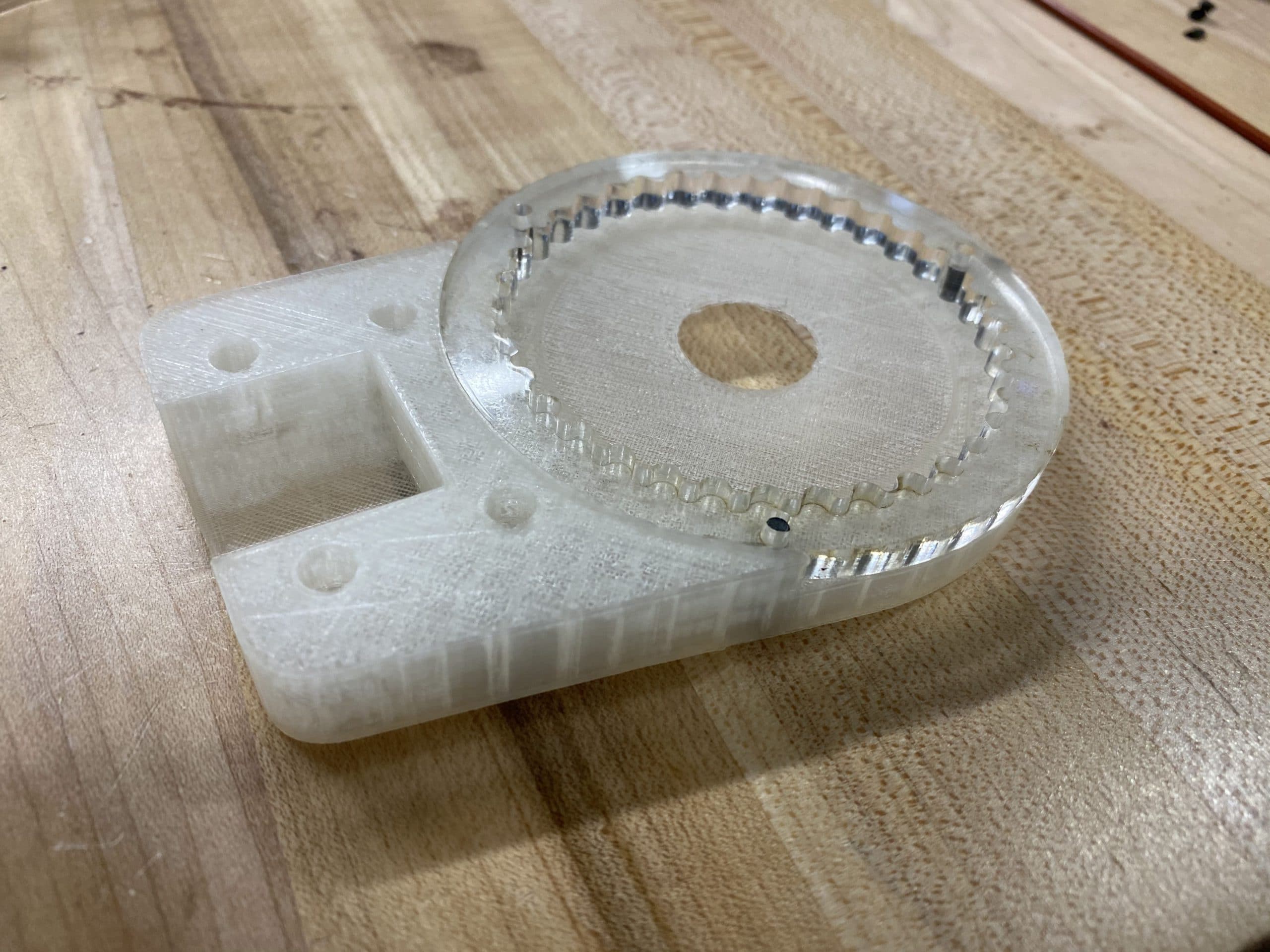
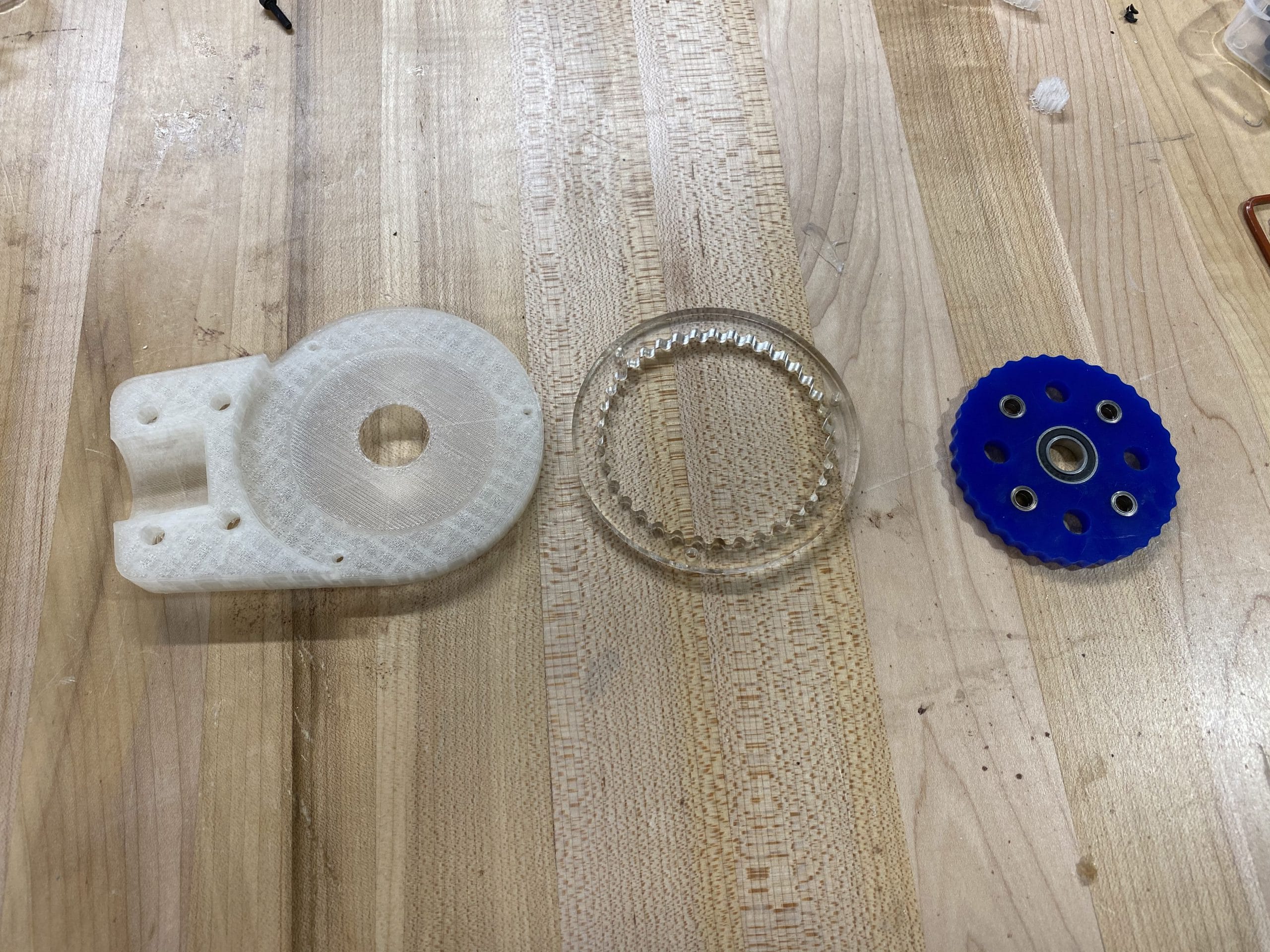
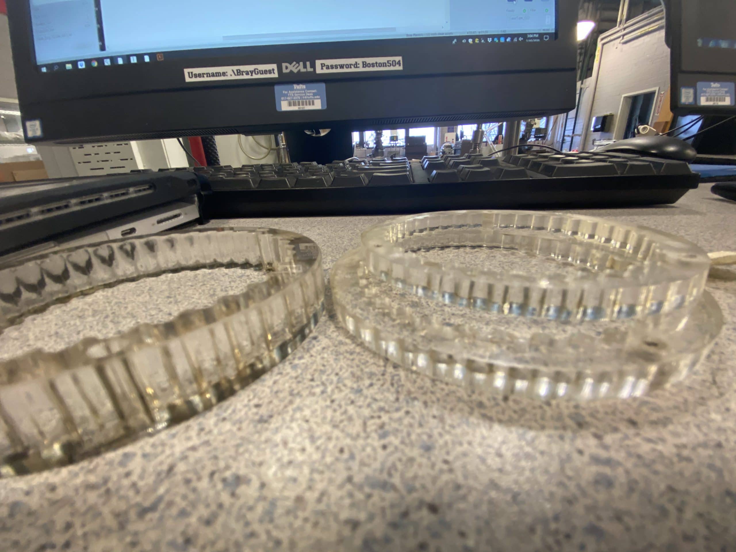
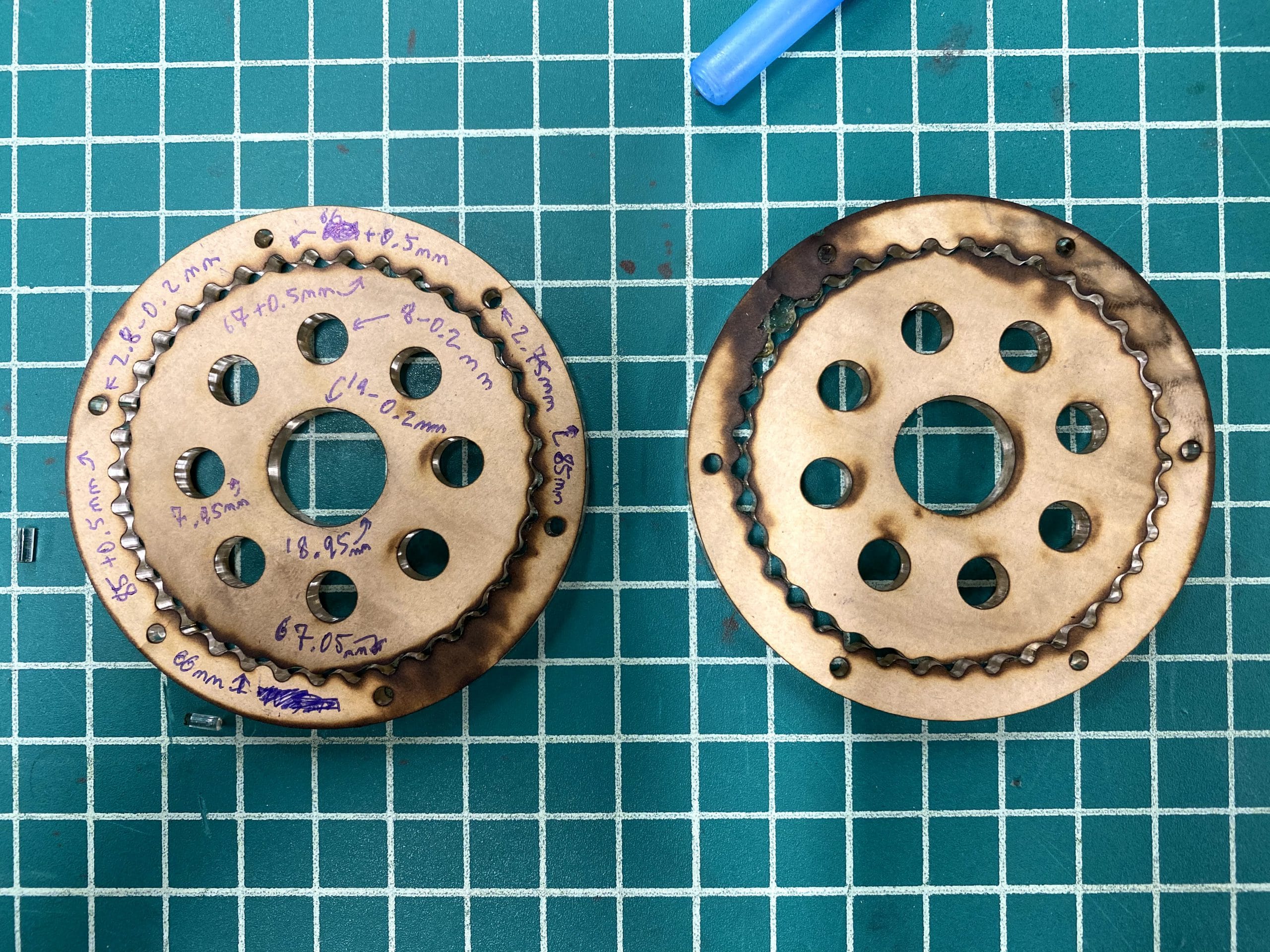
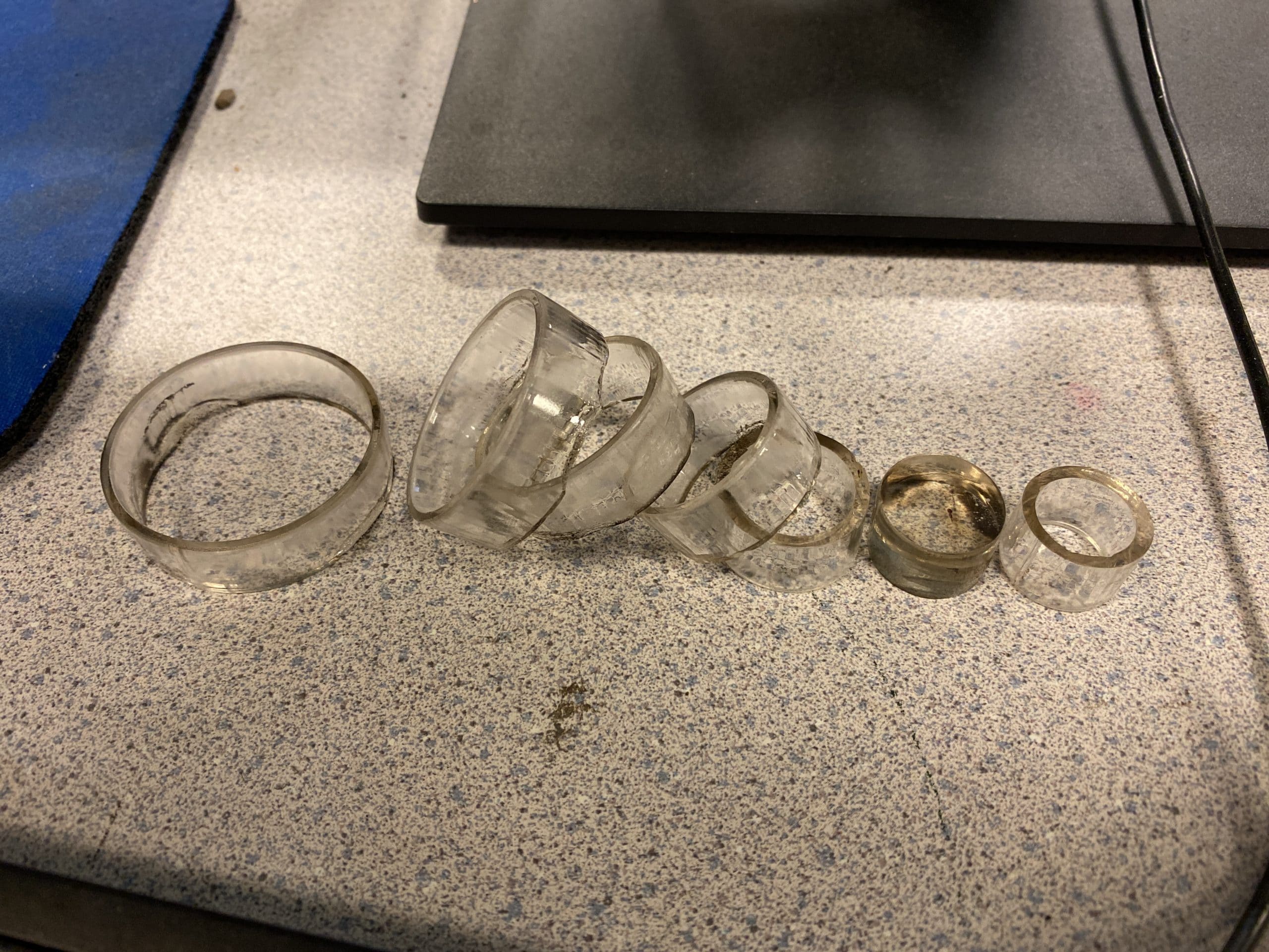
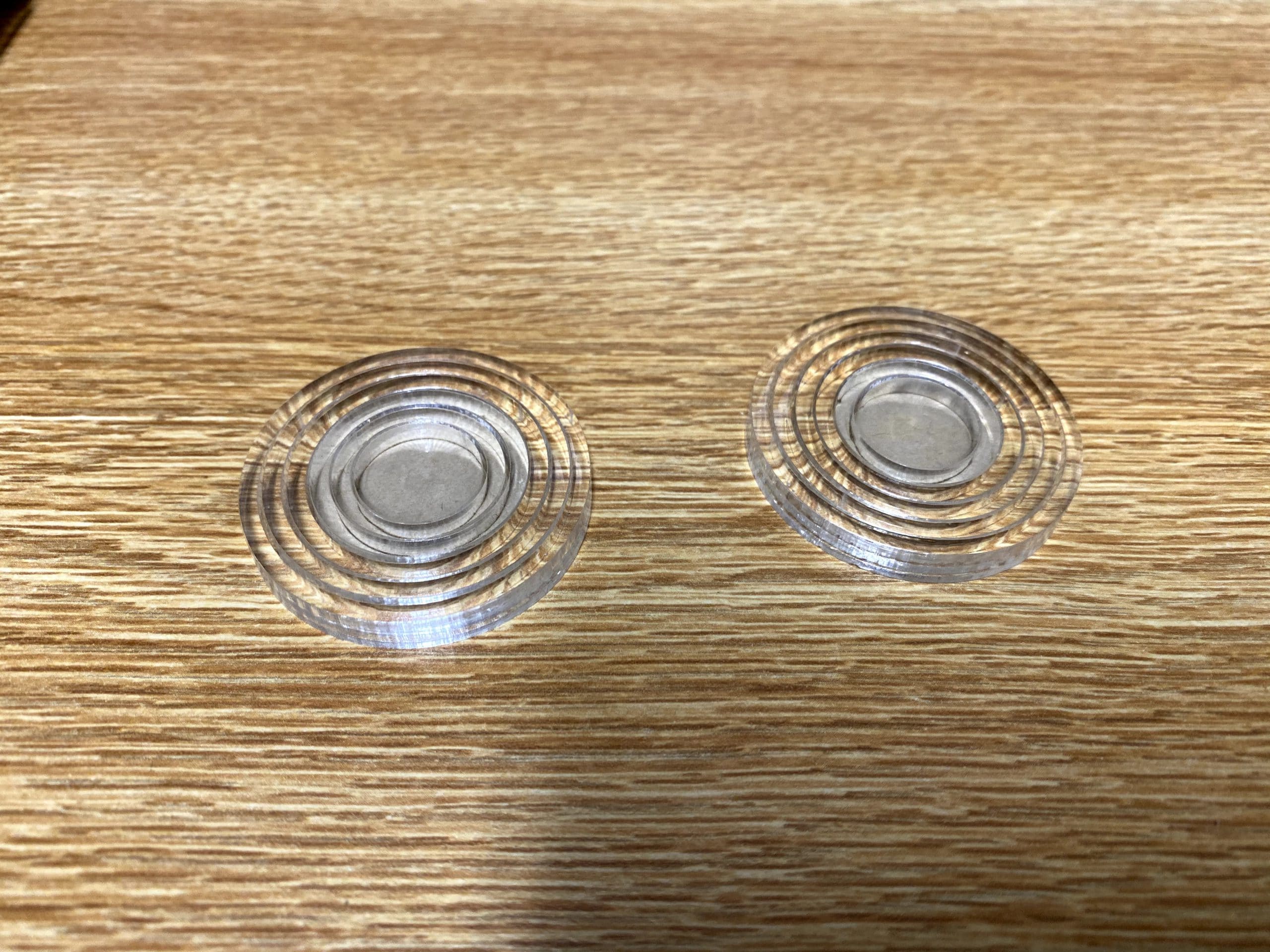
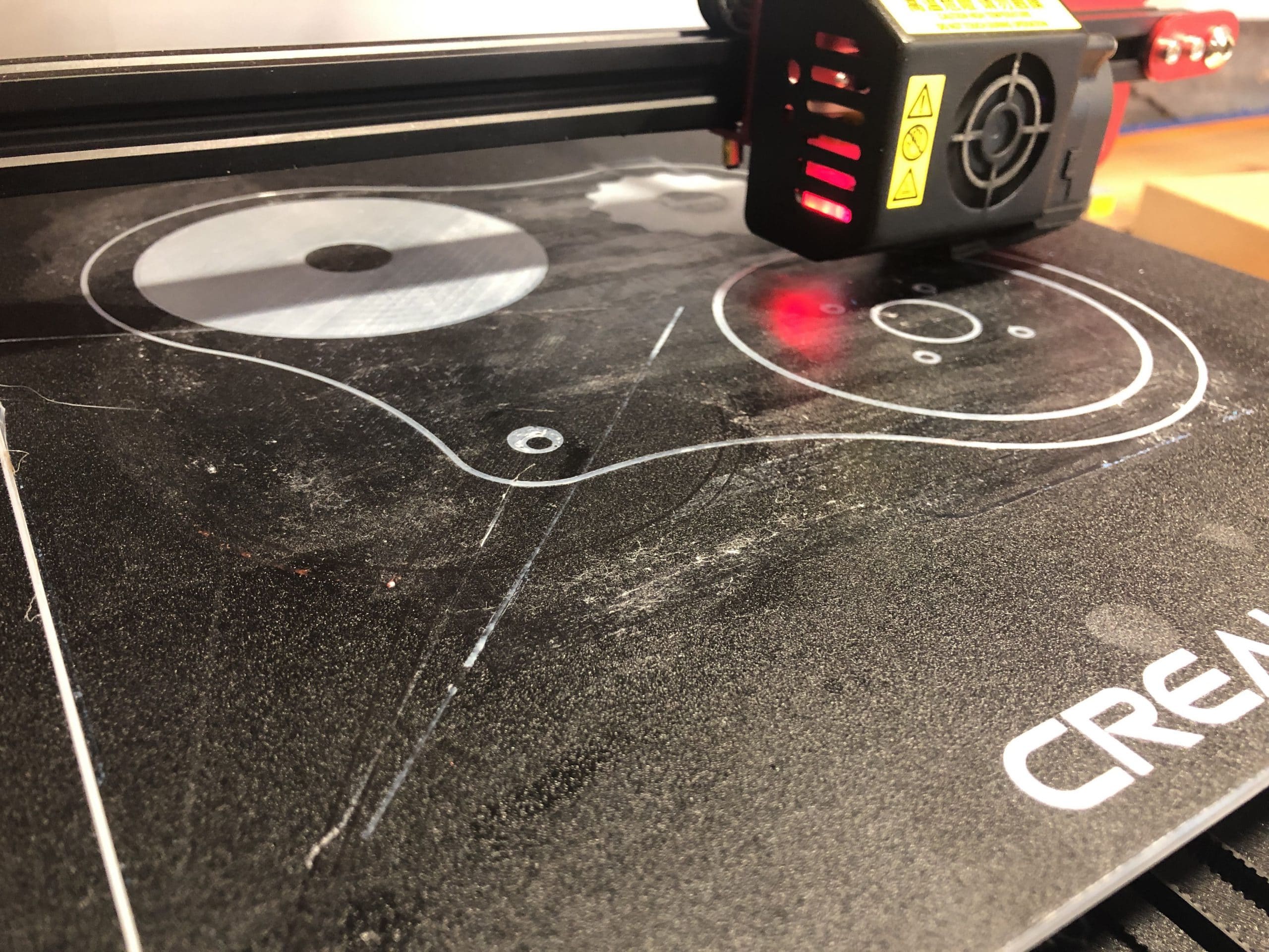
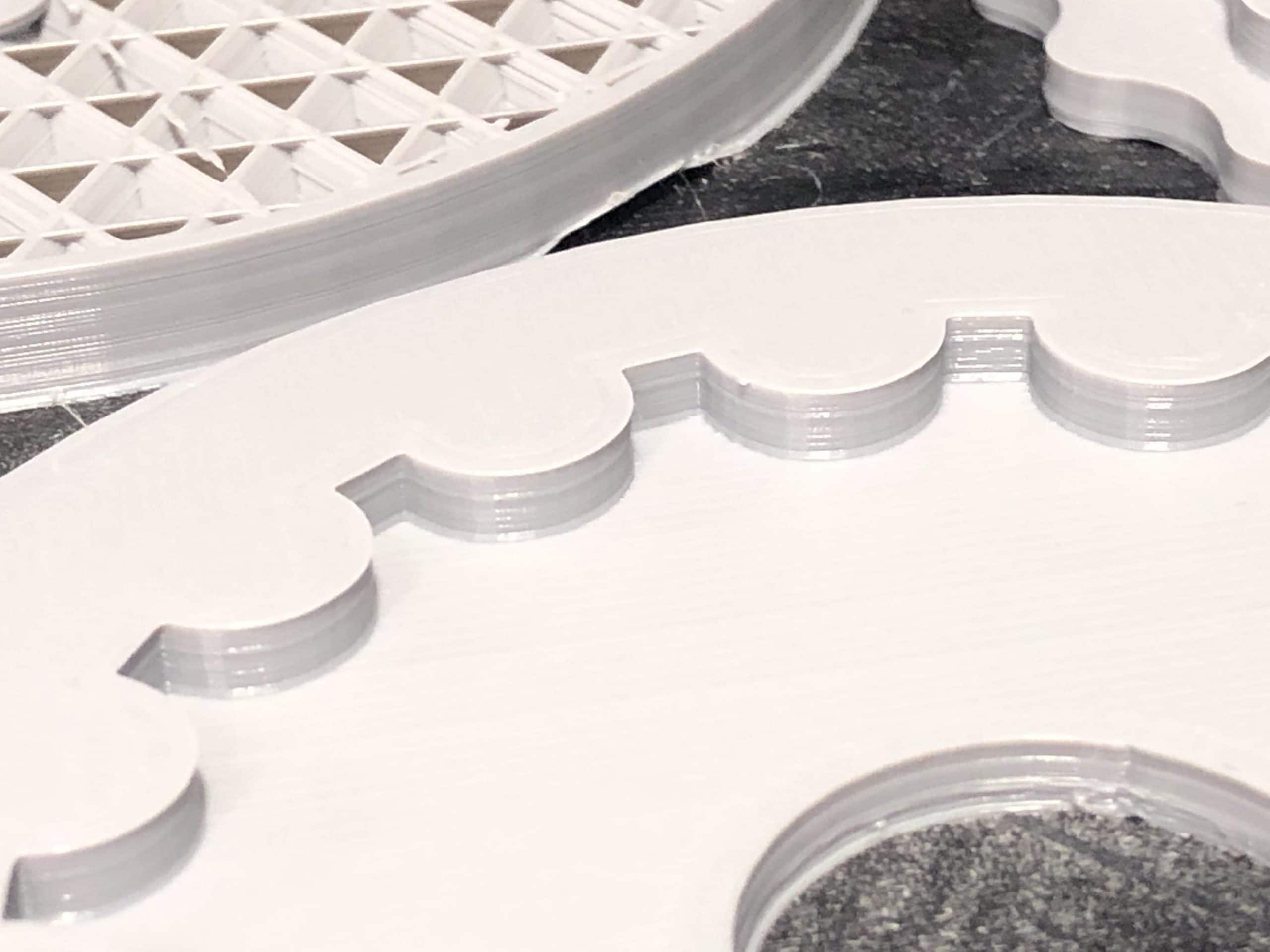
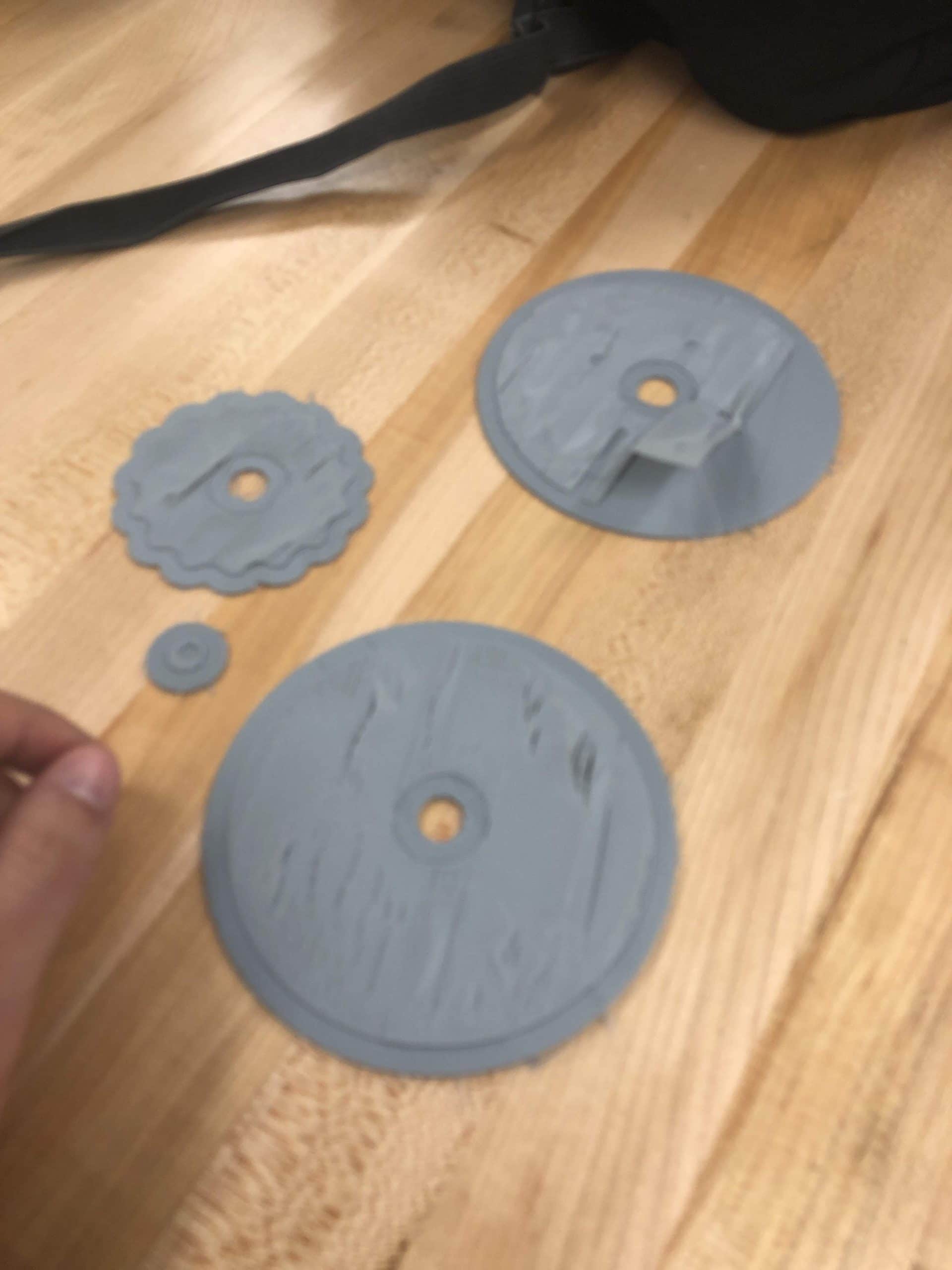
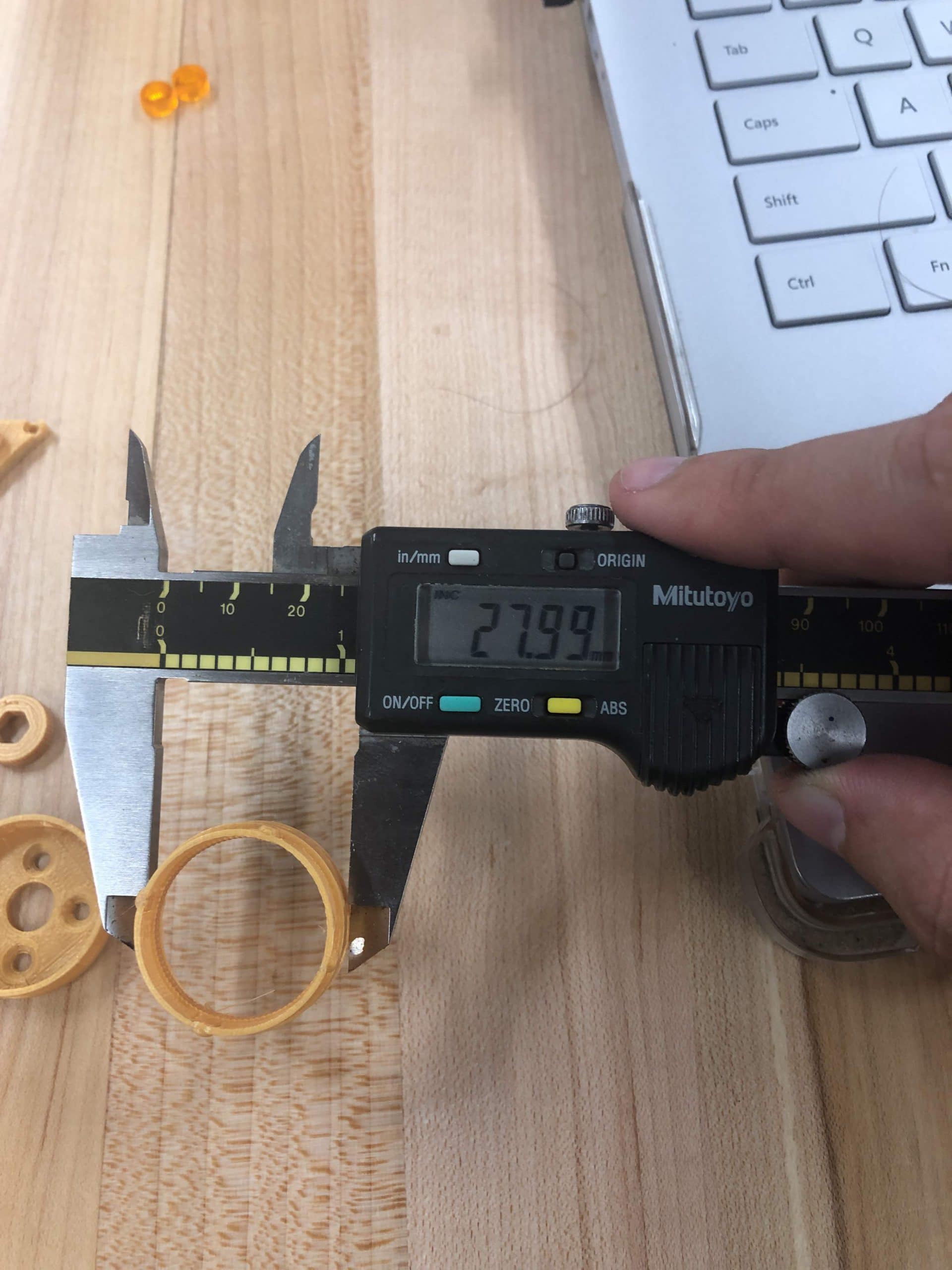
- Softening blue acrylic gears with heat to reduce the likilhood of cracking the gear while inserting the XXXX bearings with the bearing press. Using spare acrylic parts to press the bearing down evenly also reduces damage by the bearing press on the gear. Three M3 screws secure the clear acrylic outer gear to the 3D printed gearbox output (transparent and orange versions). An orange revision of the gearbox was printed but was scrapped partially due to slicer induced defects. Also pictured are a number of dimensionally inaccurate gears and a defective outer gear ring cut from a single piece of 12.80mm acrylic. Also pictured are sets of concentric rings with base diameters in increments of 5mm (20, 25, 30mm, etc) with offsets of 0.1mm (20, 25.1, 30.2mm, etc) used to identify the required offset to laser cut dimensionally accurate parts.
Design Developments
- 1.0mm cylindrical ribs to secure carbon fiber tubes
- Gearbox Output separated into acrylic and PLA components
Electrical Developments
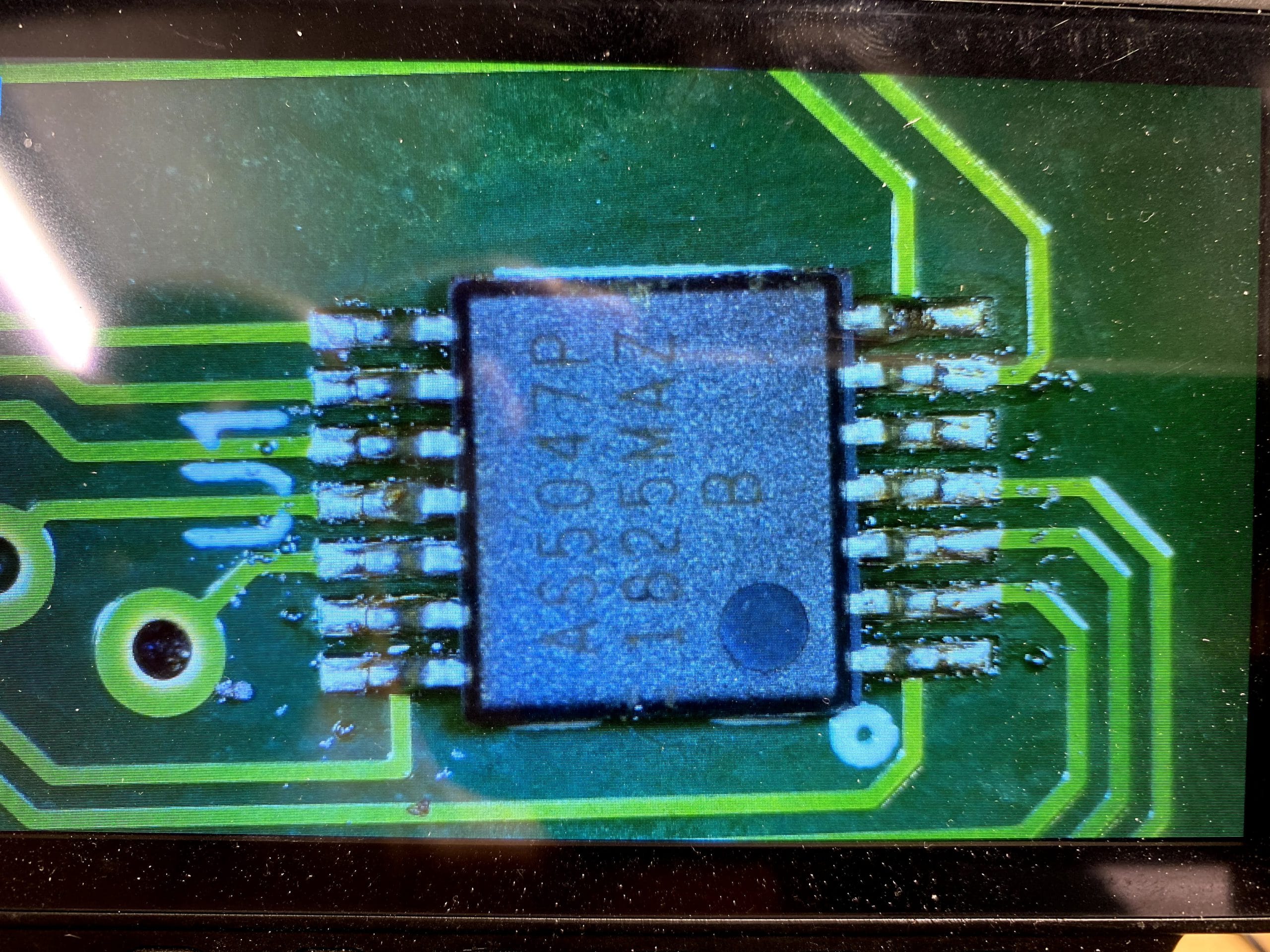
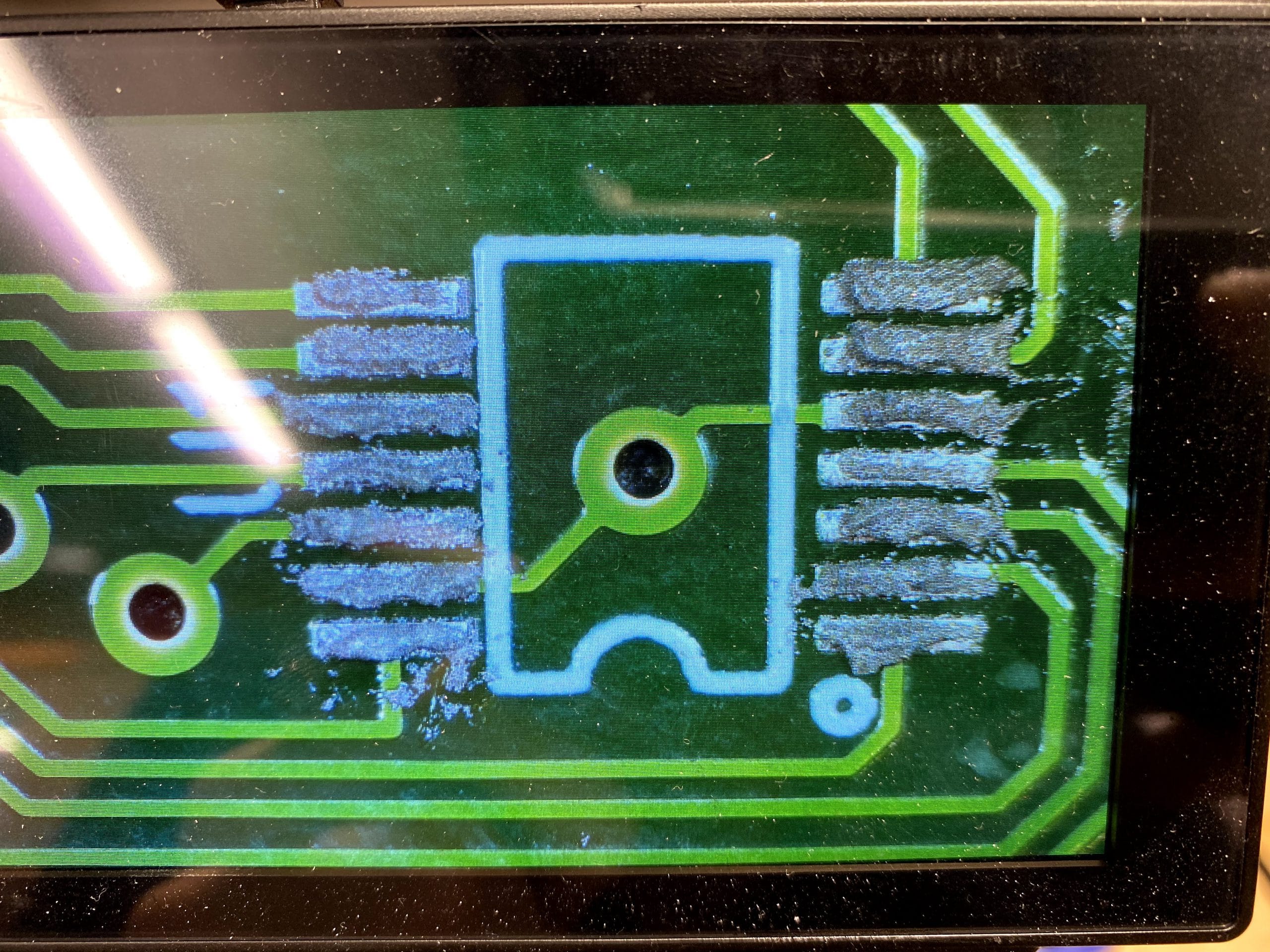
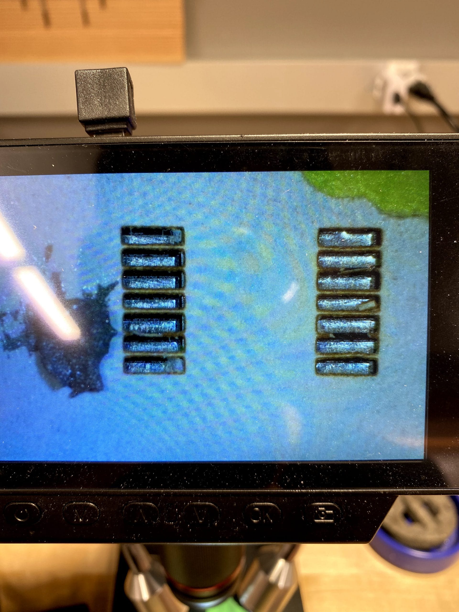
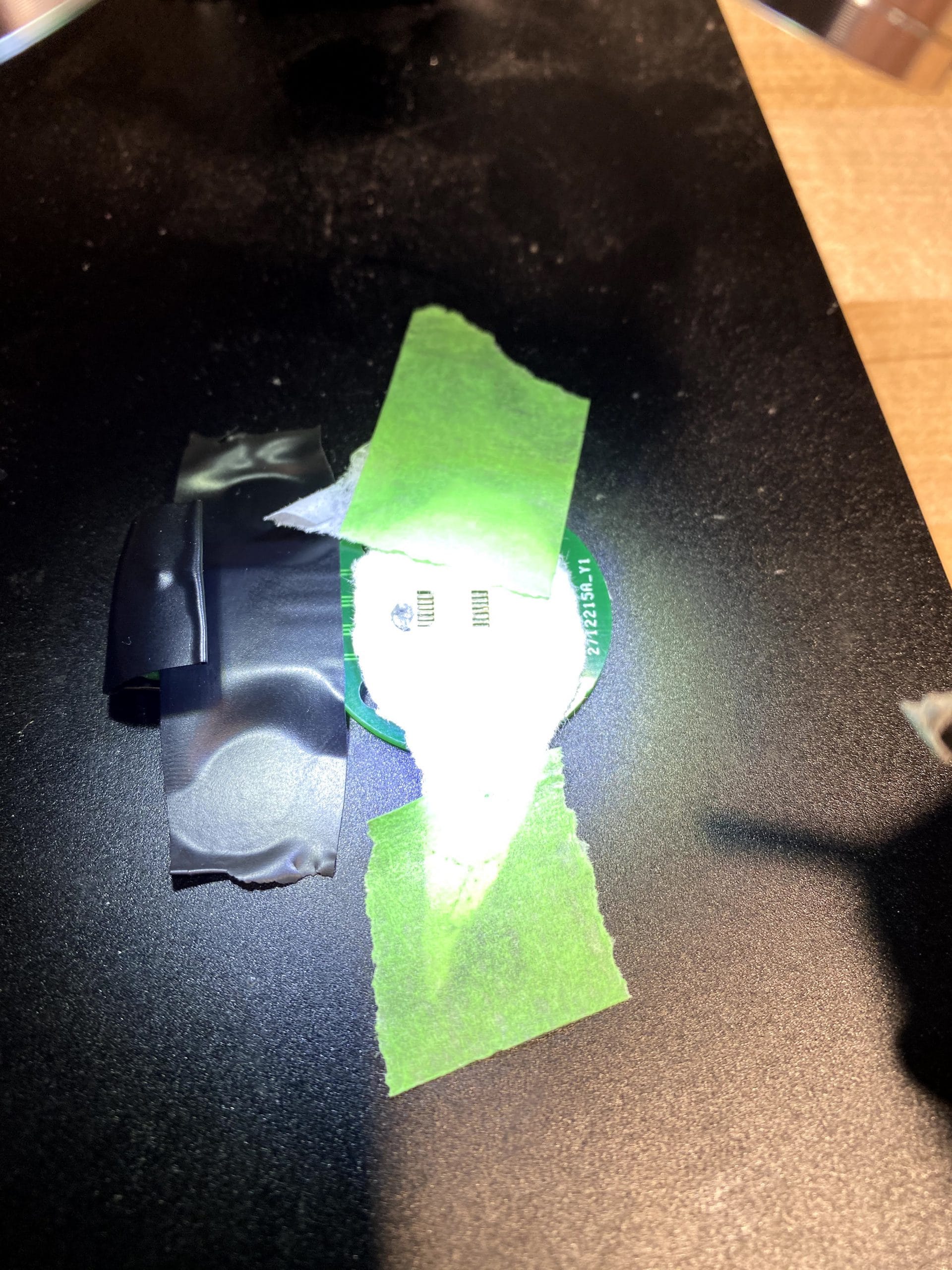
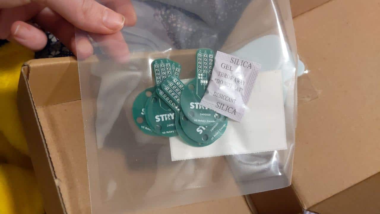
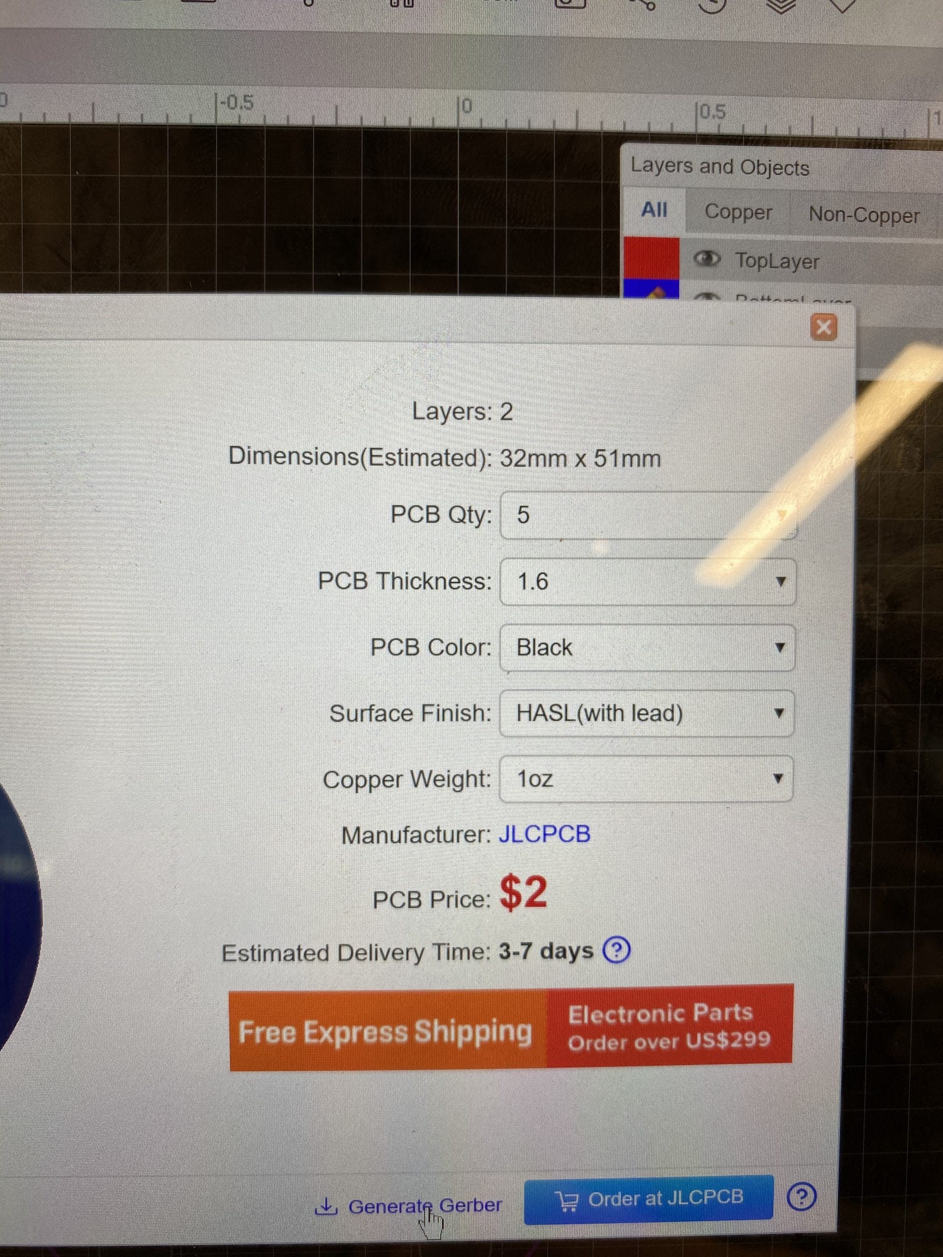
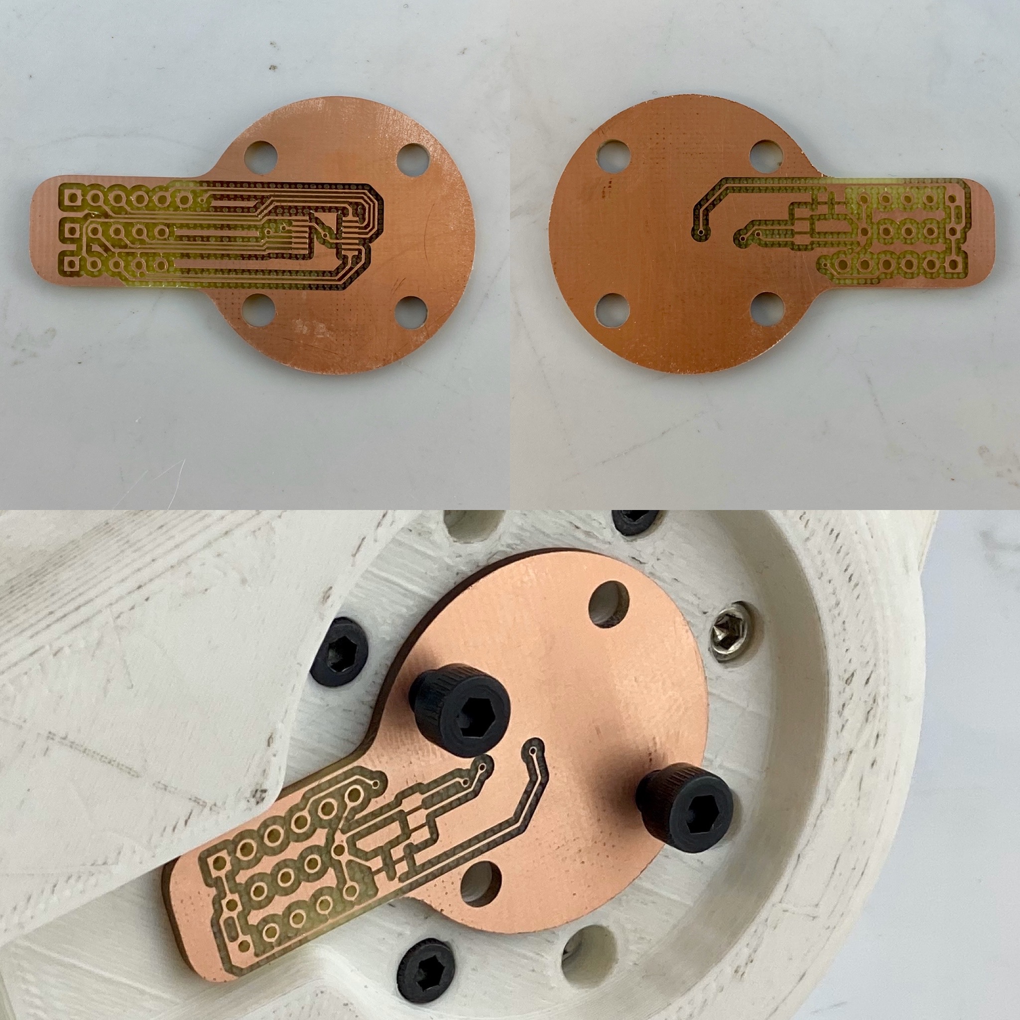
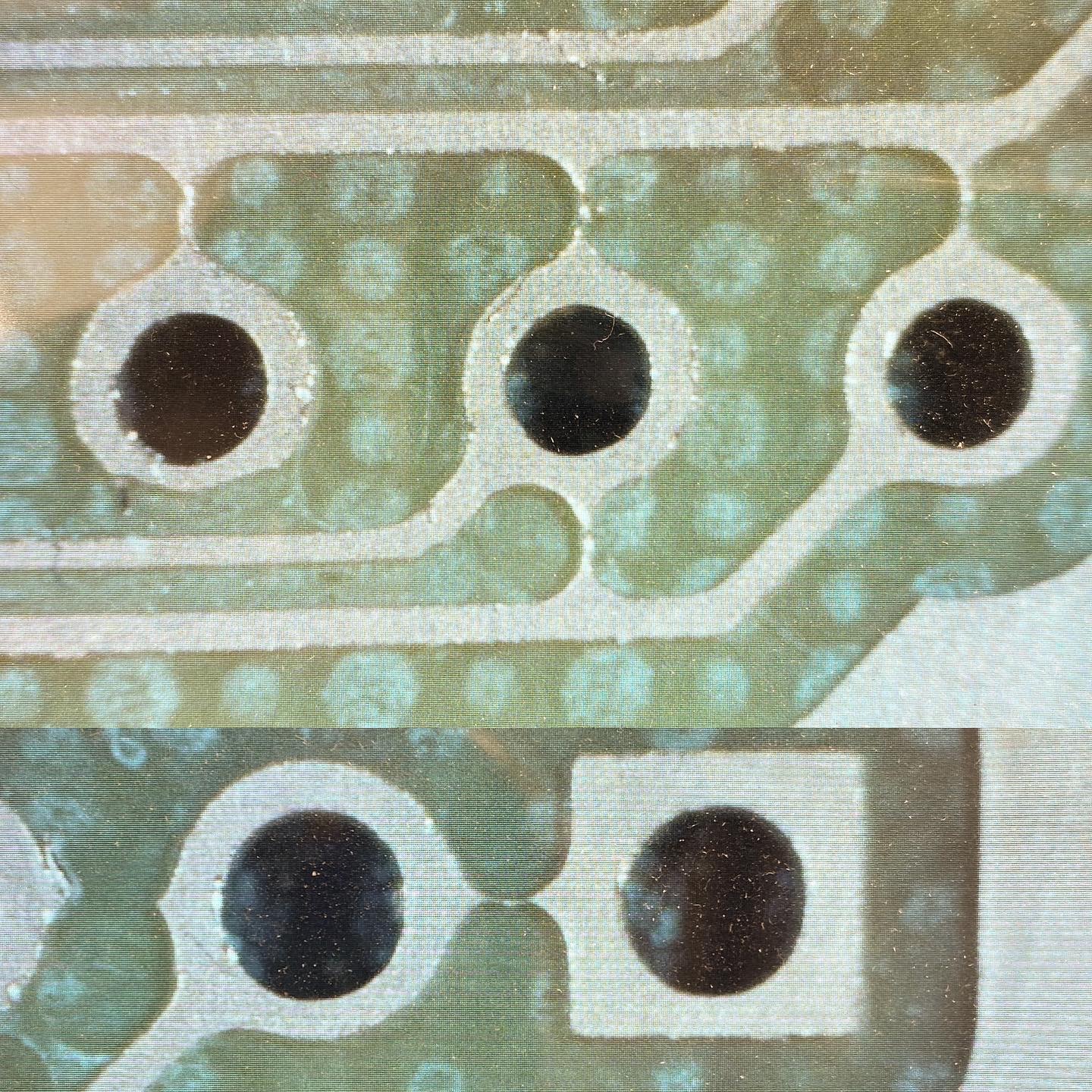
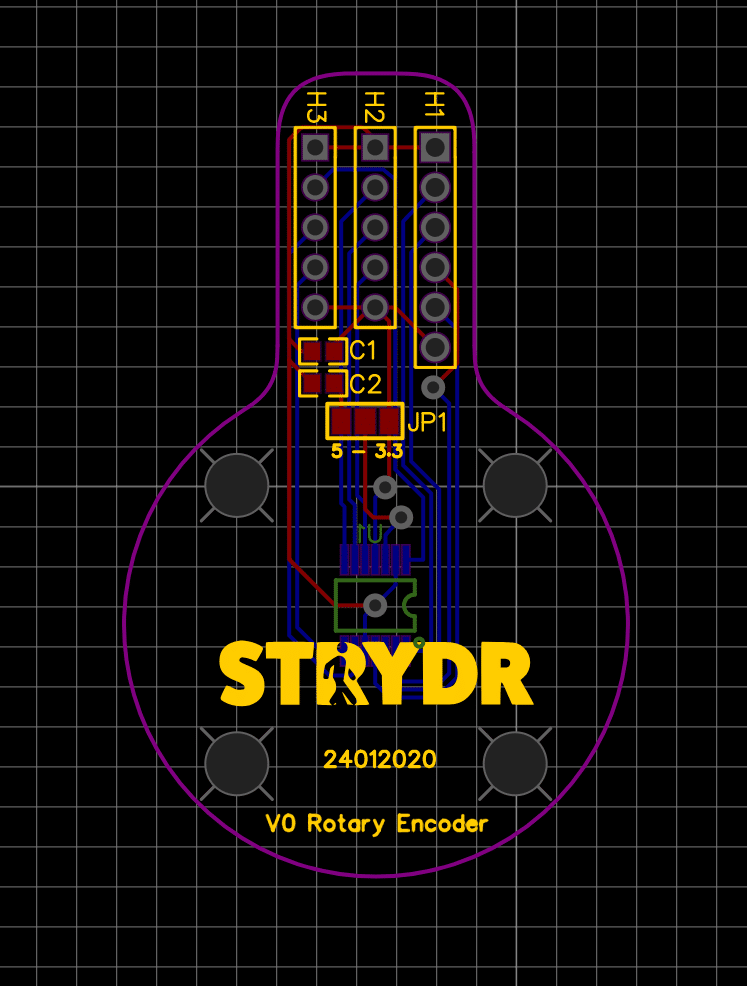
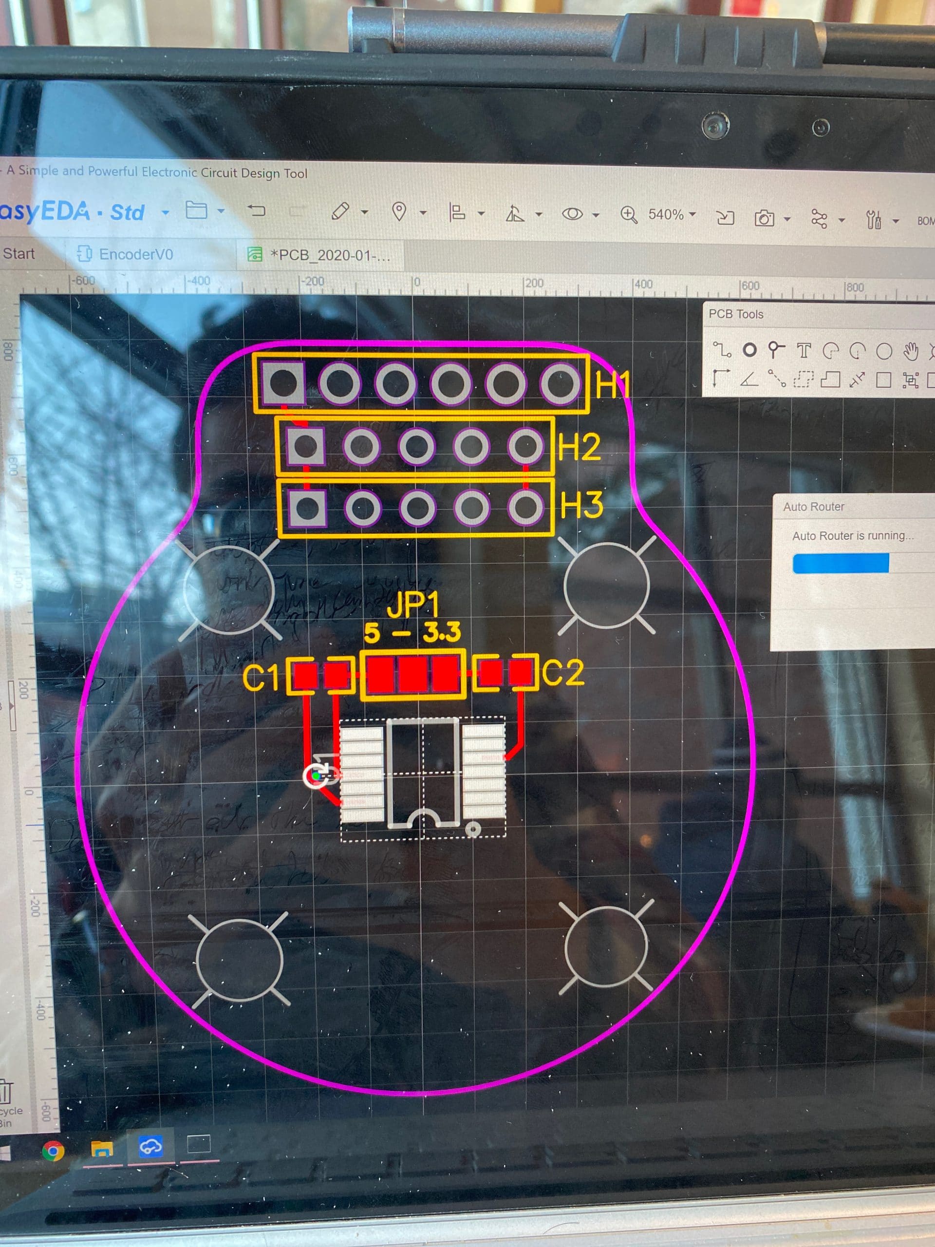
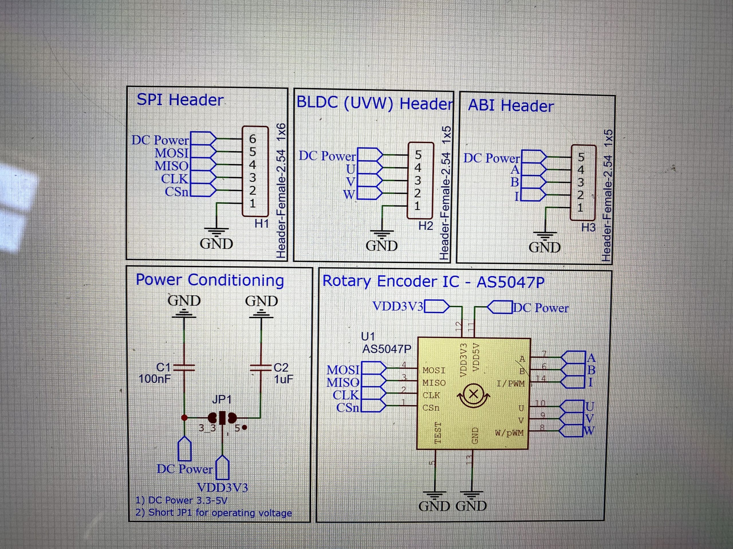
- Rotary encoder position on PCB corrected.
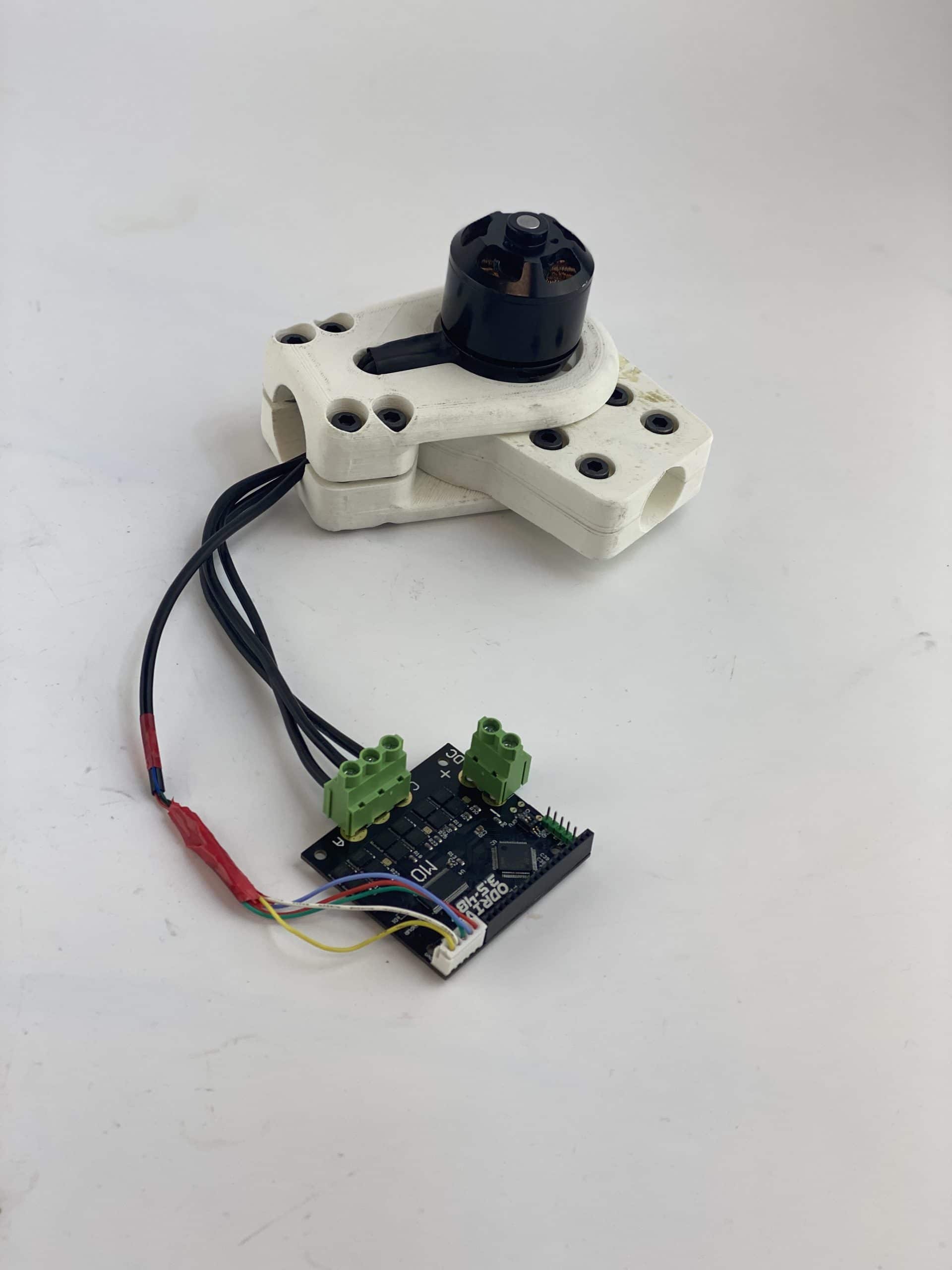
- oDrive startup protocol configured.
Manufacturing Developments
- Laser Cut 5.5mm Cast Acrylic Gearbox
- Laser Cut 12.80mm Cast Acrylic Gearbox
- FDM 3D printed housing
- SLA 3D printed CAM shaft
")
")
")


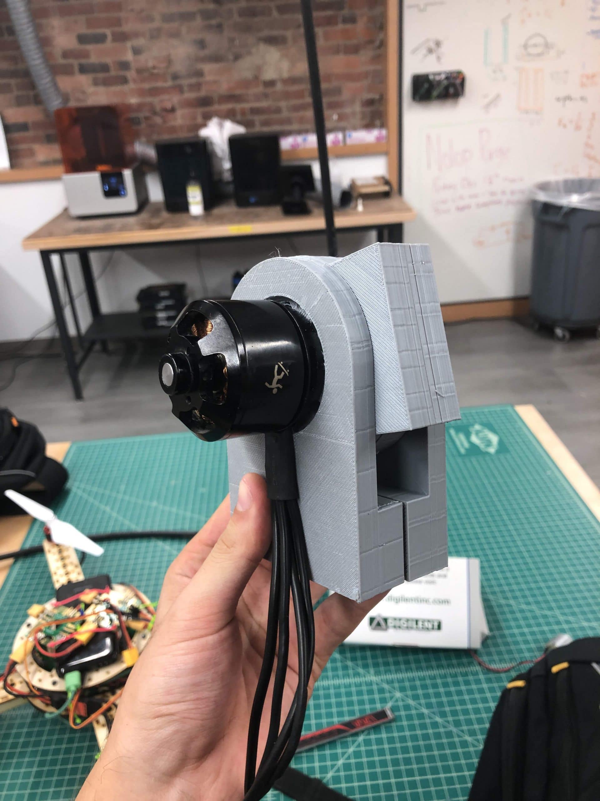
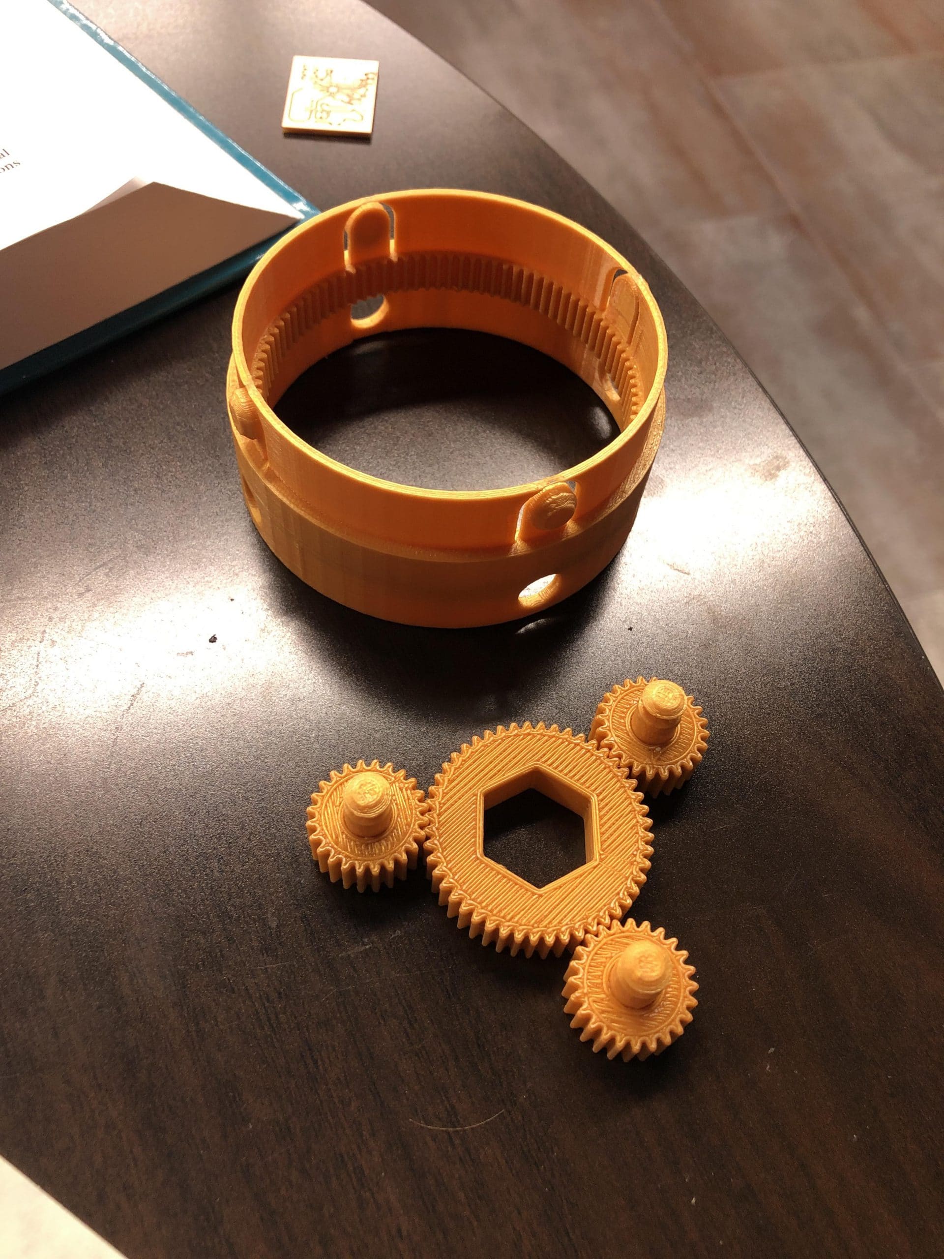
Revision 3 & 4 – Cycloidal Actuator Tweaking
- Wooo! It works!
- It looks amazing!
- It is kinda prone to clogging, but everything fits together as planned.
Design Developments
- Smoothed Geometry (Continuous Curvature where possible)
- Gearbox features mount point for carbon fiber frame
Electrical Developments
- FDM 3D printed gears, gearbox, and enclosure
- Integrated 200kV 3-Phase BLDC motor with M4 Screws
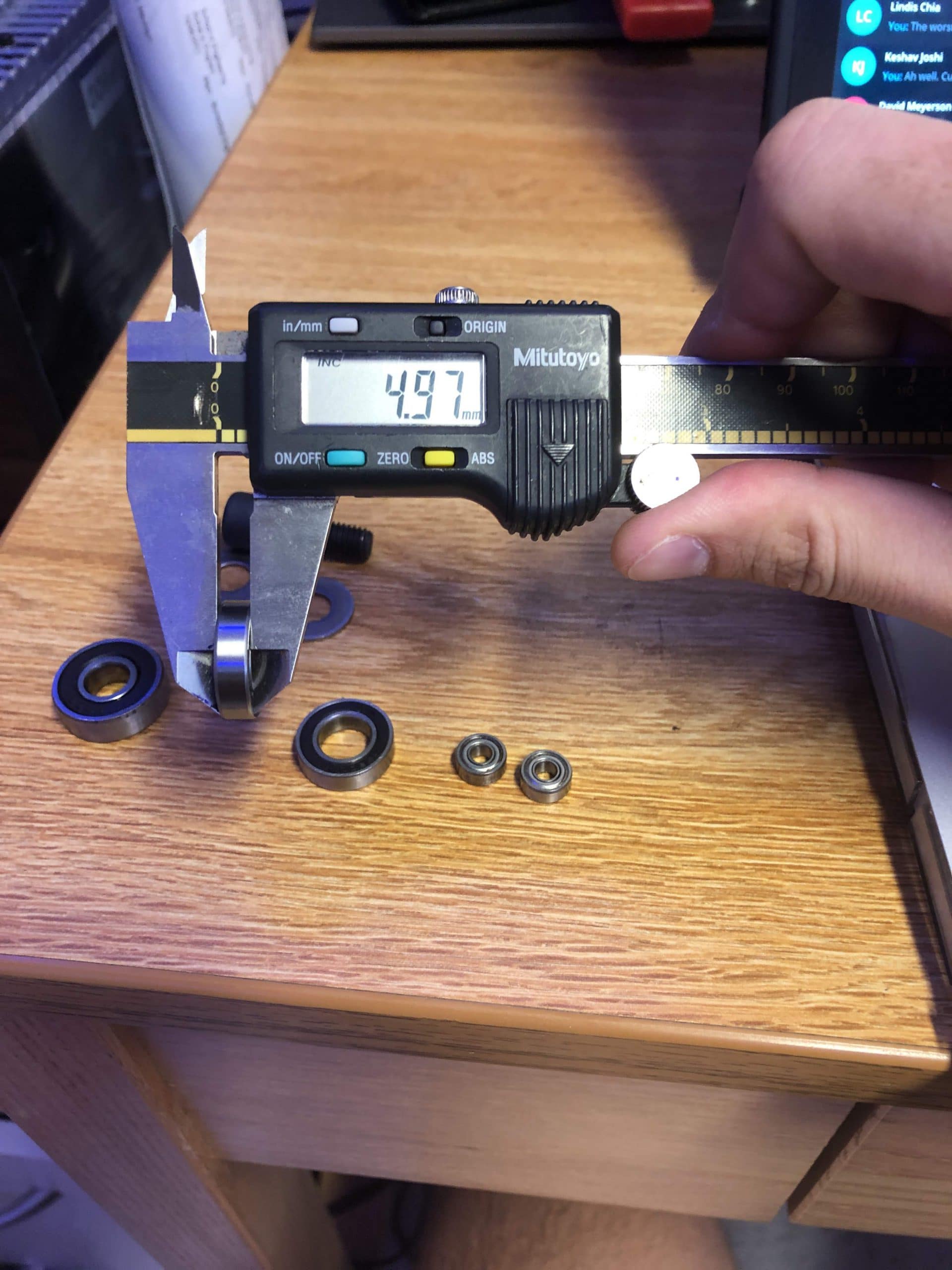
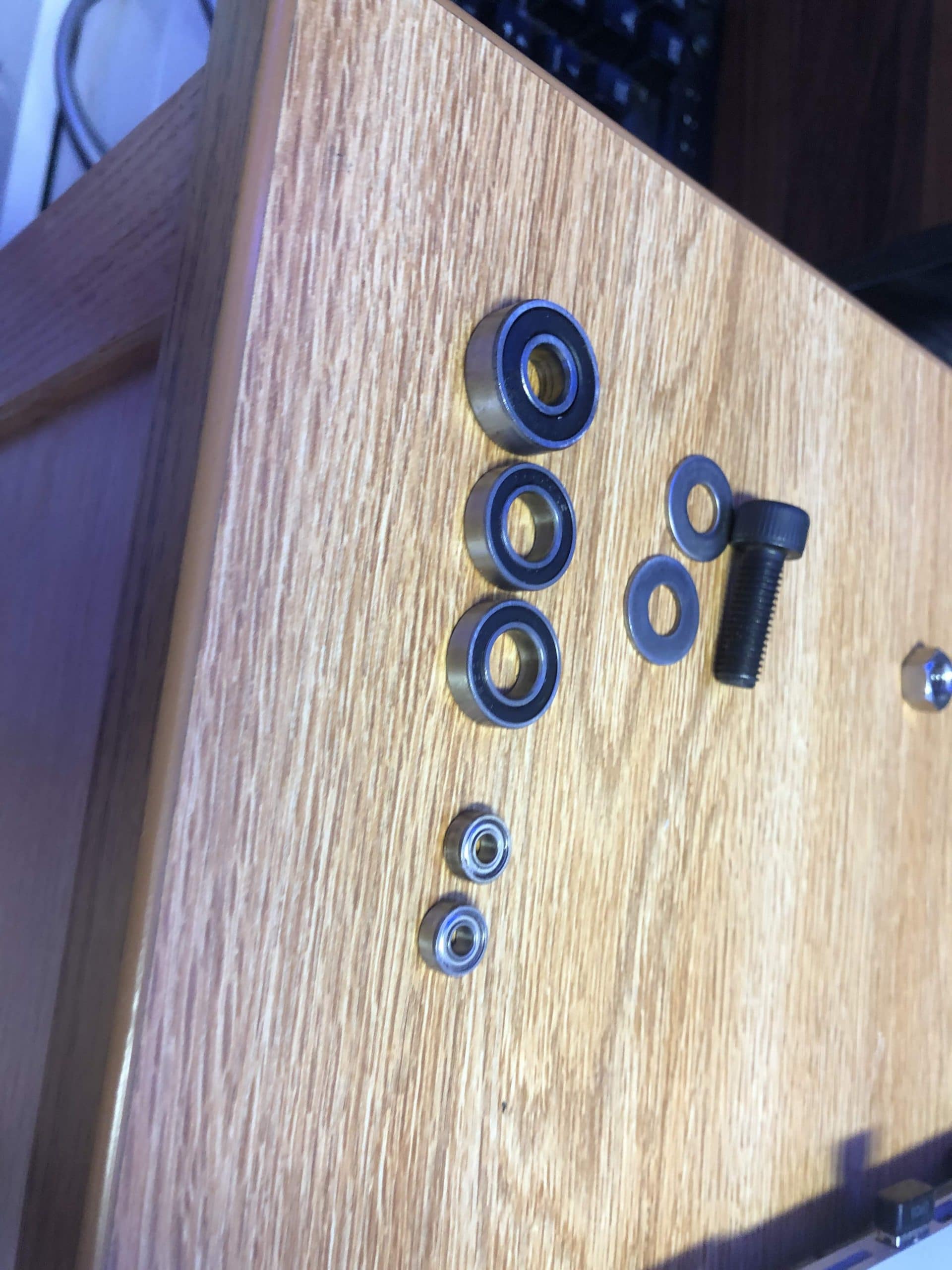
- Integrated 608 bearings
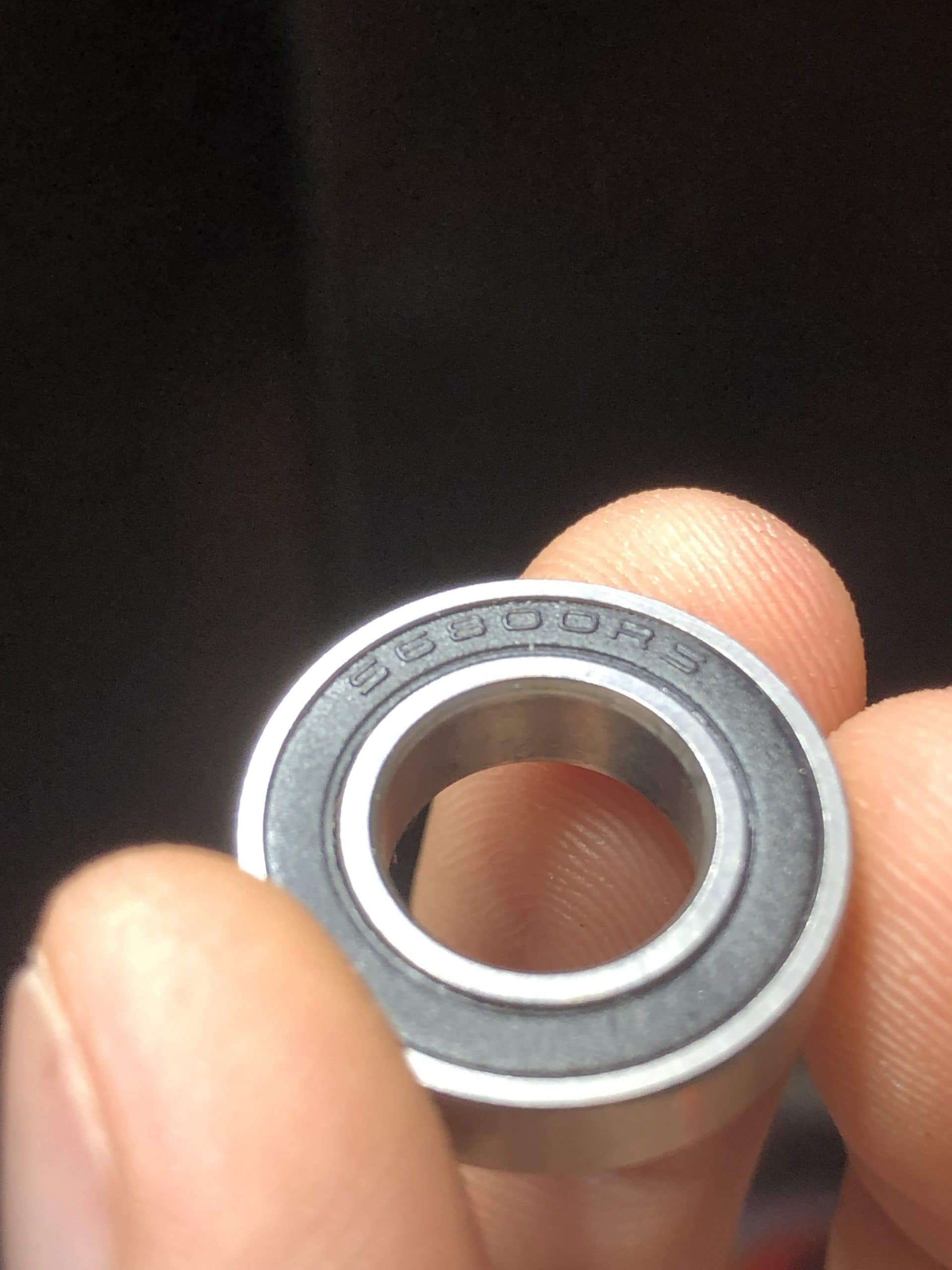
- Integrated XXXX bearings
- Integrated XXXX bearings
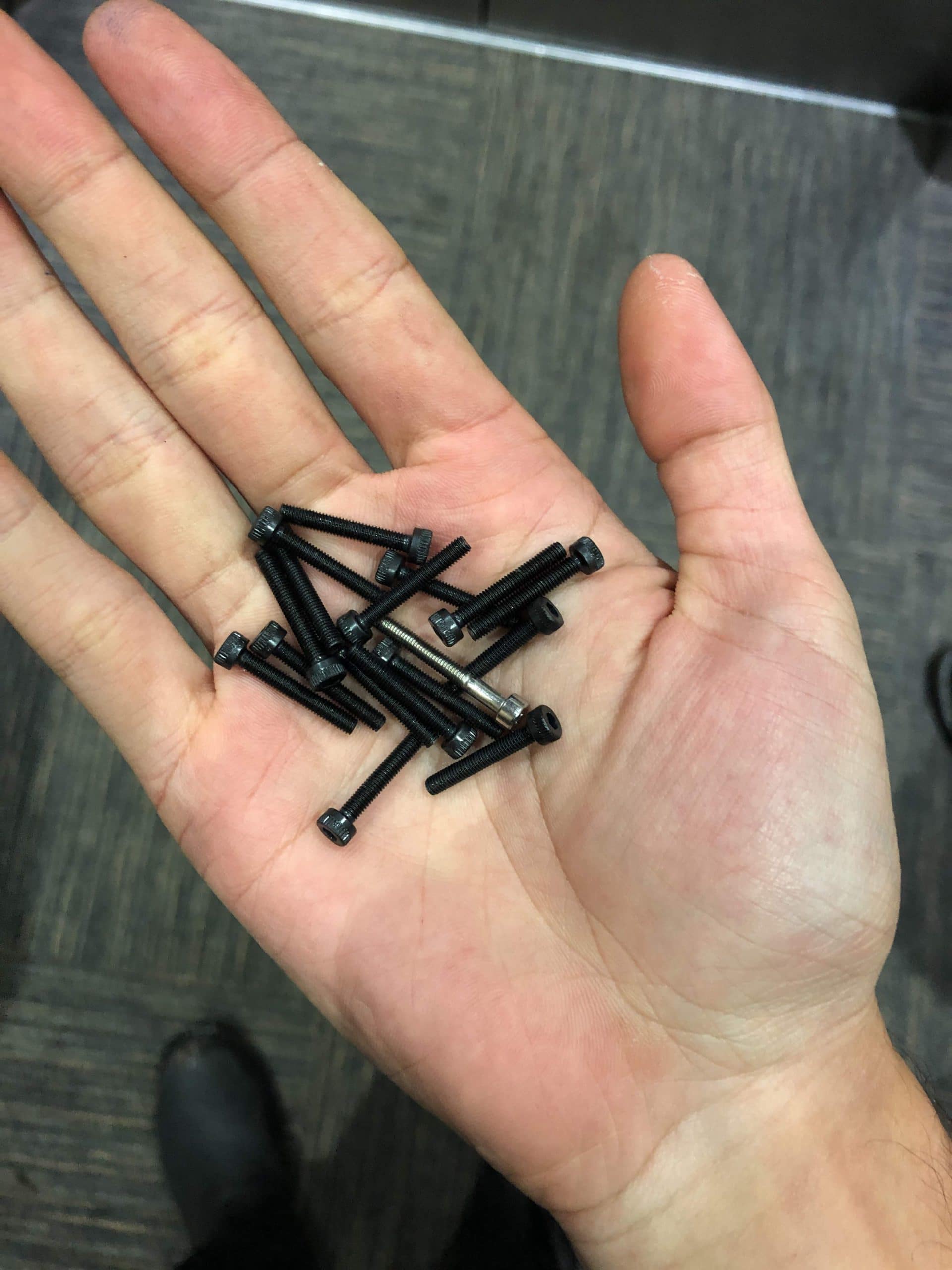
- Integrated M3x25 screws as roller pins
- Integrated Carbon fiber tubes
Manufacturing Developments
- BLDC Controller Selection
- VESC firmware requires significant revision to operate in closed loop.
- oDrive (almost identical in hardware to VESC) is suited for application.
- BLDC Motor Selection
- 200kV (200 Rotations per volt)
- 3Nm torque generated by phase current of 72 Amps
- Internal 120 Degree Offset Hall Effect Sensors for controlled startup


")

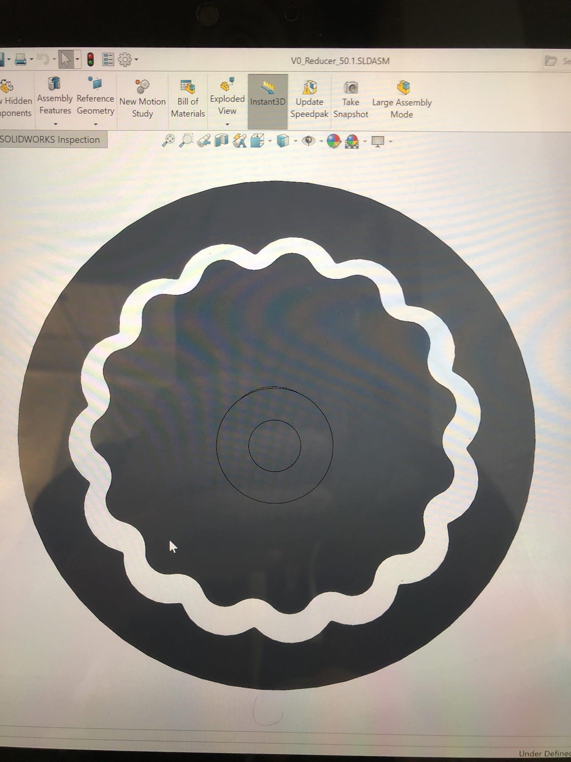
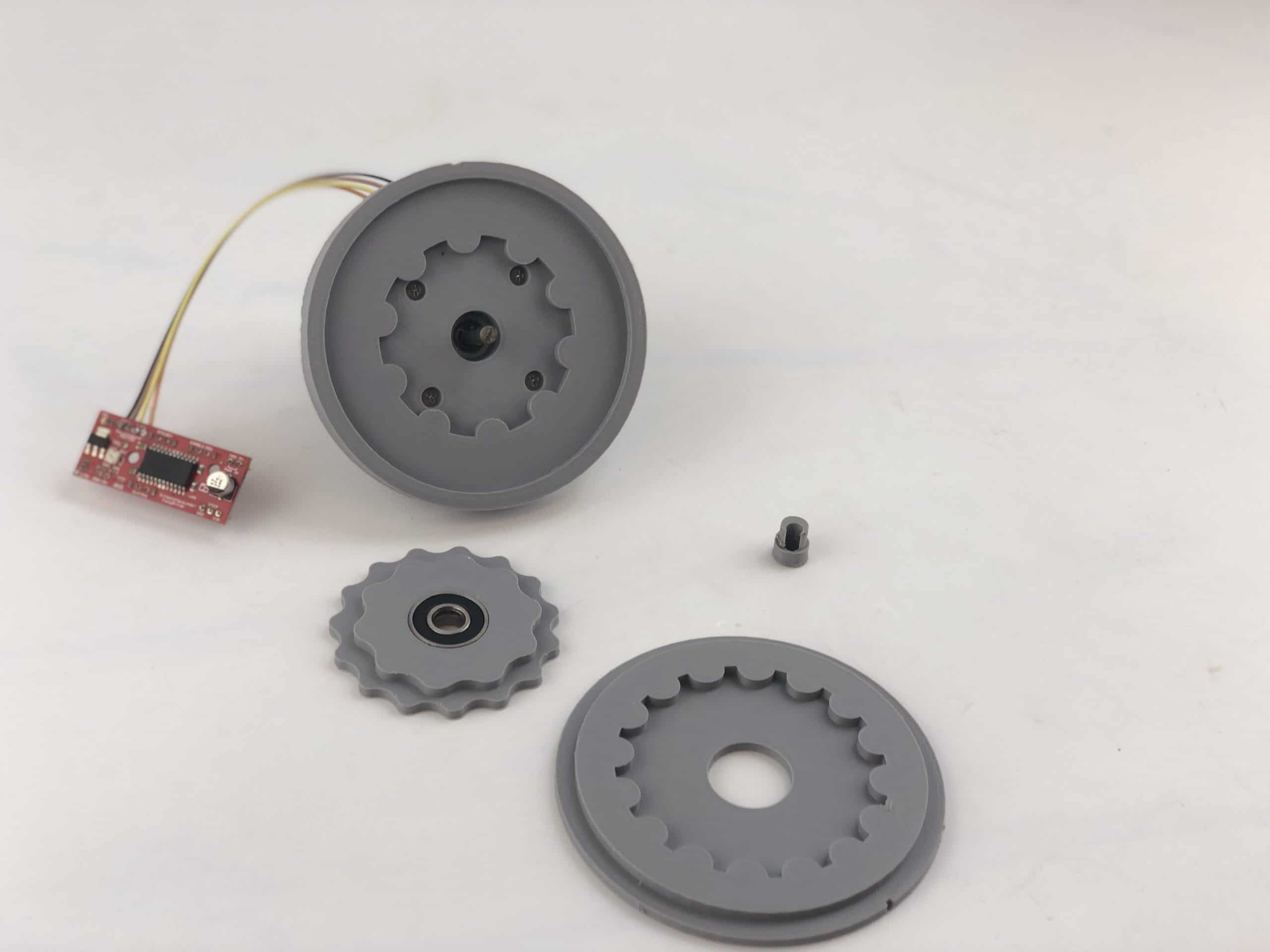
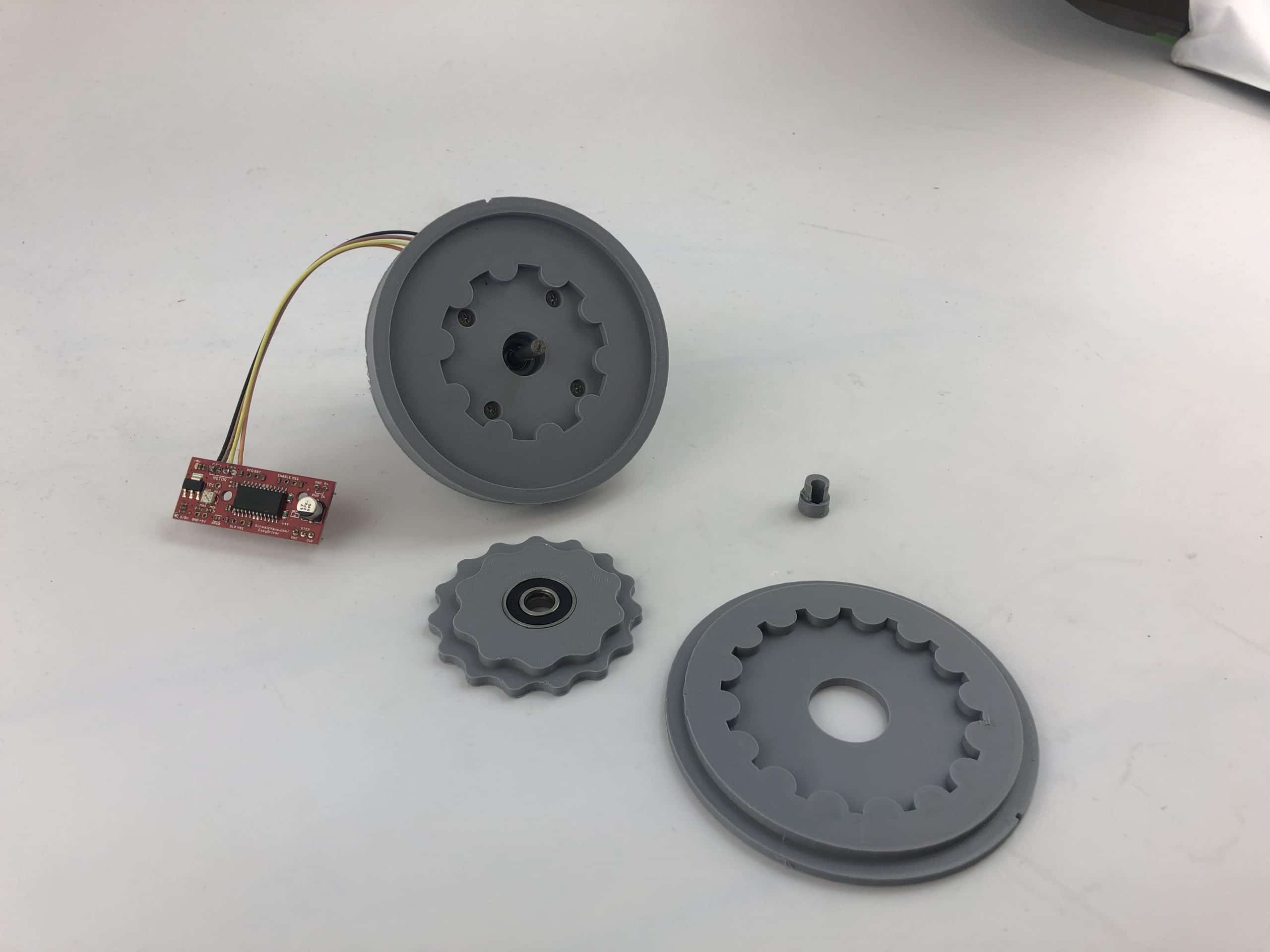
Revision 2 – Proof of Concept Cycloidal Drive
- The design of this gearbox follows a more conventional cycloidal reducer design. The first design demonstrated hypocycloidal motion wherein a gear rolls within a fixed gear and the motion of a gear lobe can be modeled with a HypoCycloid Curve. The new design demonstrates more traditional cycloidal motion wherein the outer ring gear of larger diameter and tooth count than the central gear is rotated without slipping about the circumference of the center gear.\r\n\r\nFrom a design perspective, reducing the number of moving parts and stages in the gearbox is critical. Therefore I opted for a Contracted Periycloidal motion wherein the central gears are unable to rotate, but can rotate the point of contact about the outer ring. Because the central gear cannot rotate, the outer ring rotates.
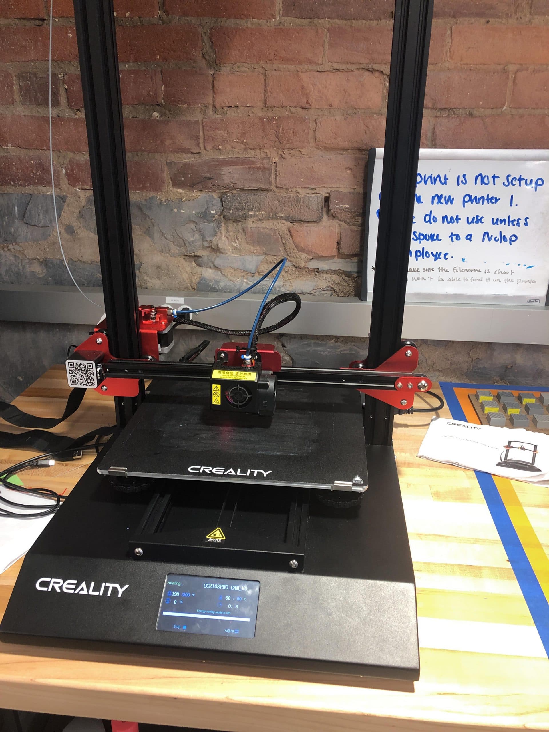
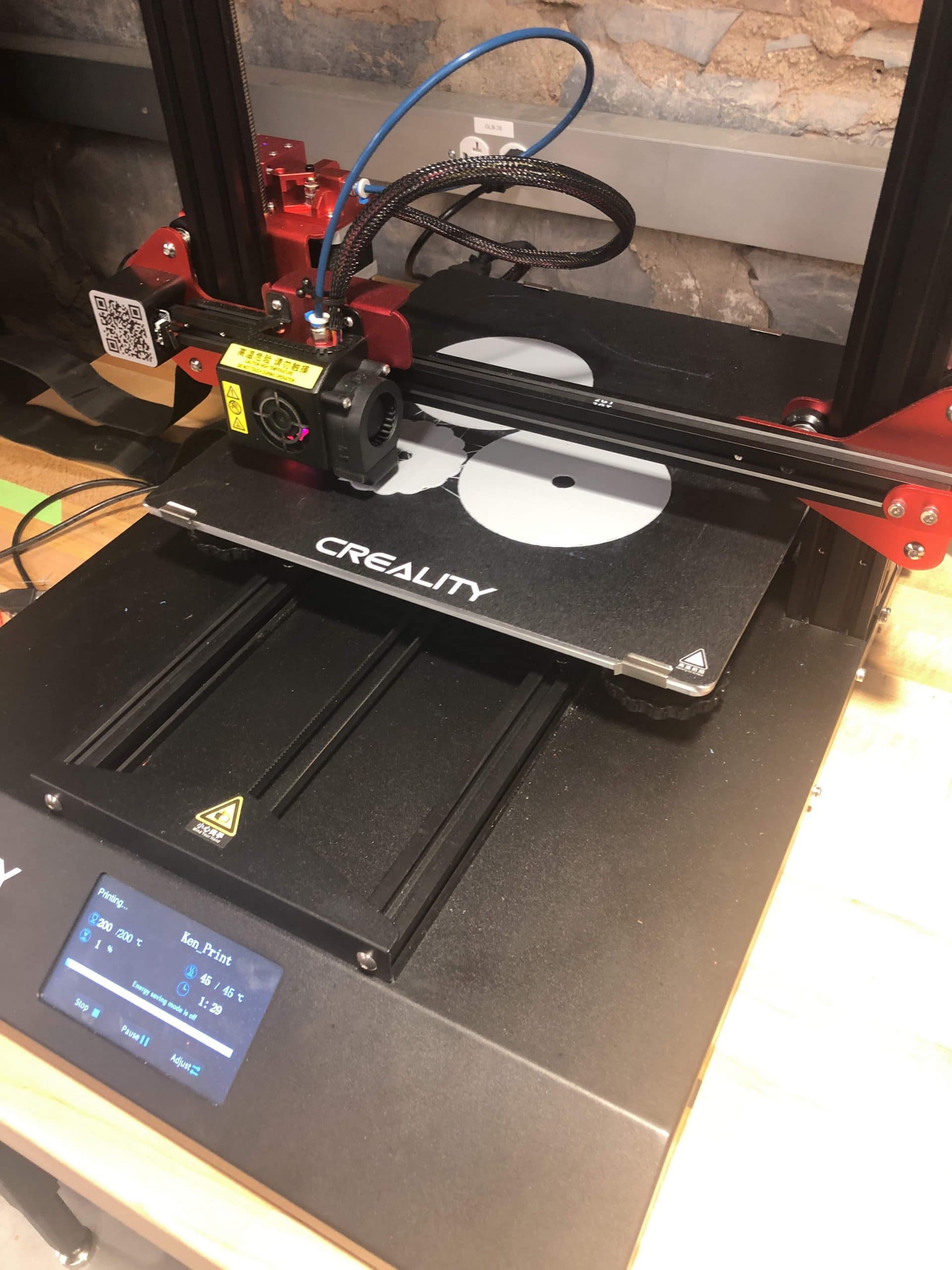
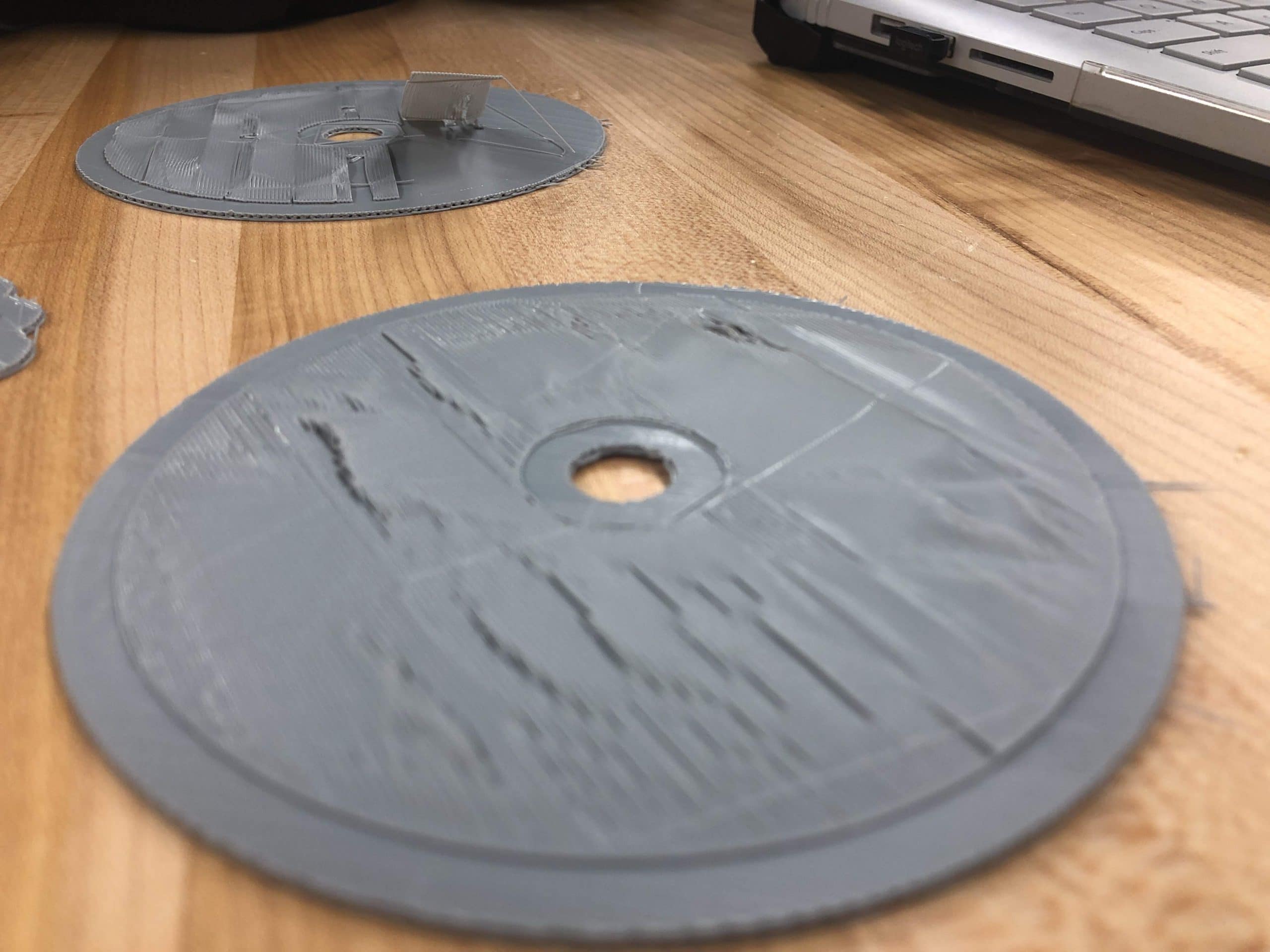
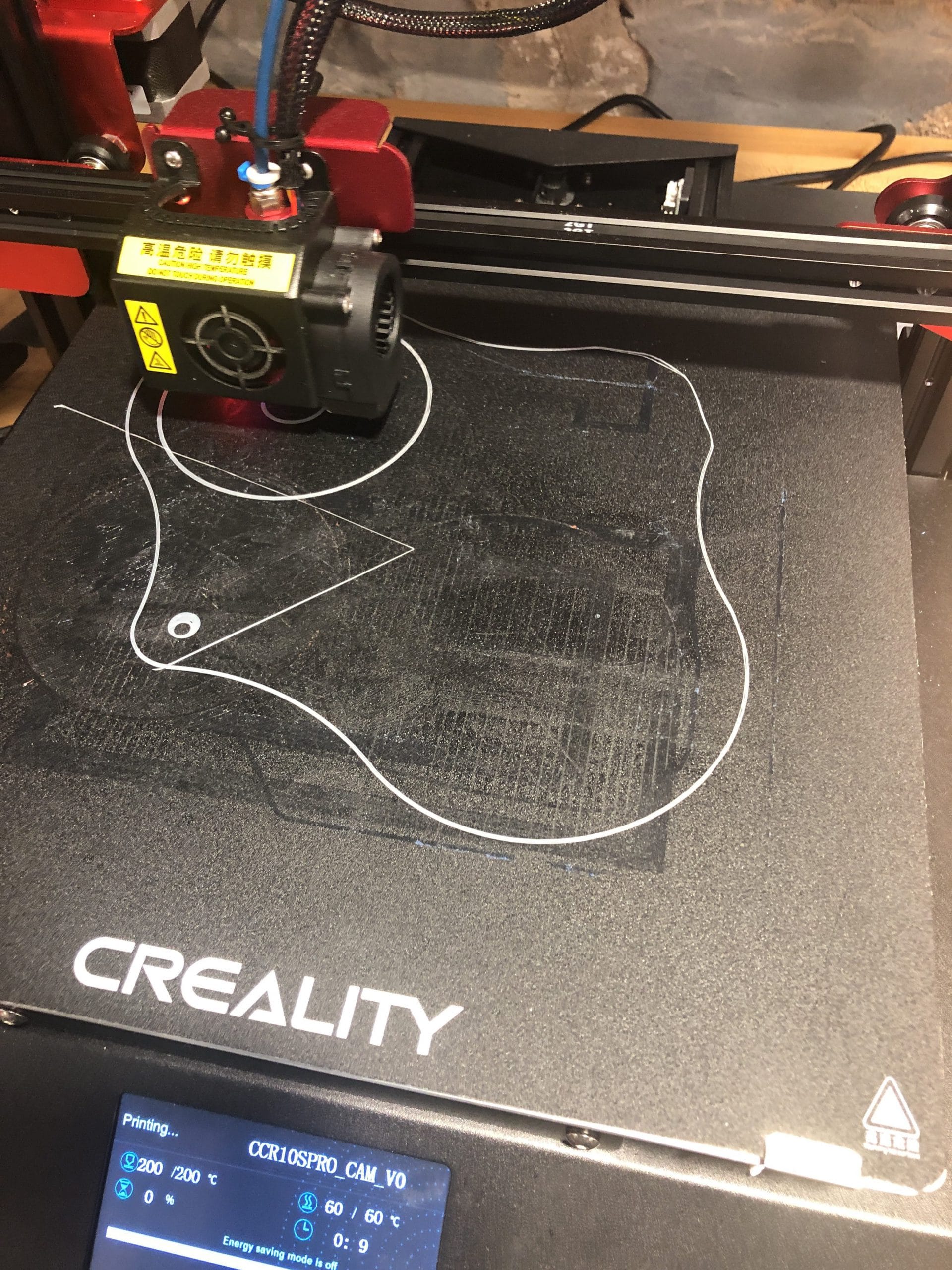
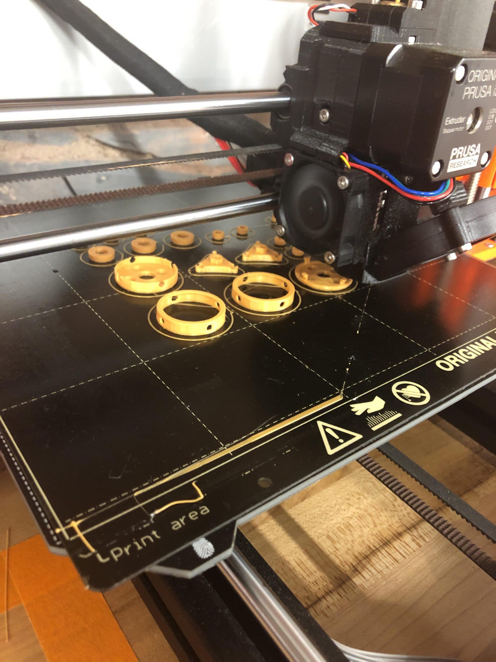
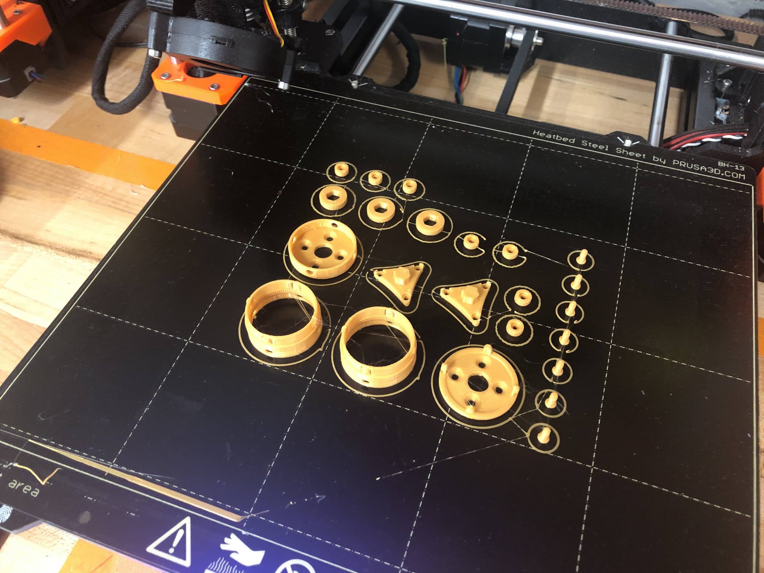
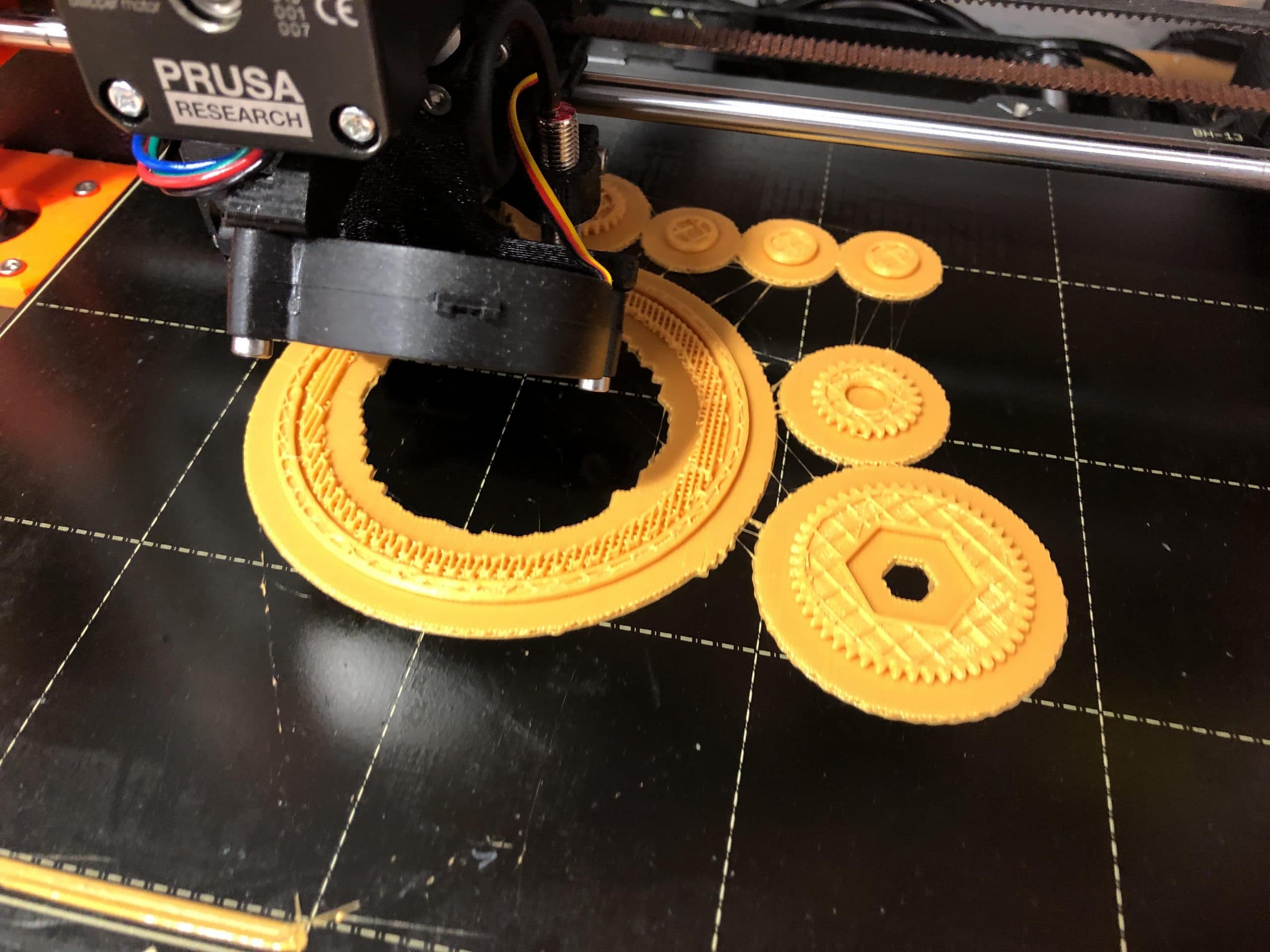
- The printers have been working non-stop during the last few weeks of the term. As such, I had to attempt more prints on the Creality printer. Once more, it posed a daunting challenge.
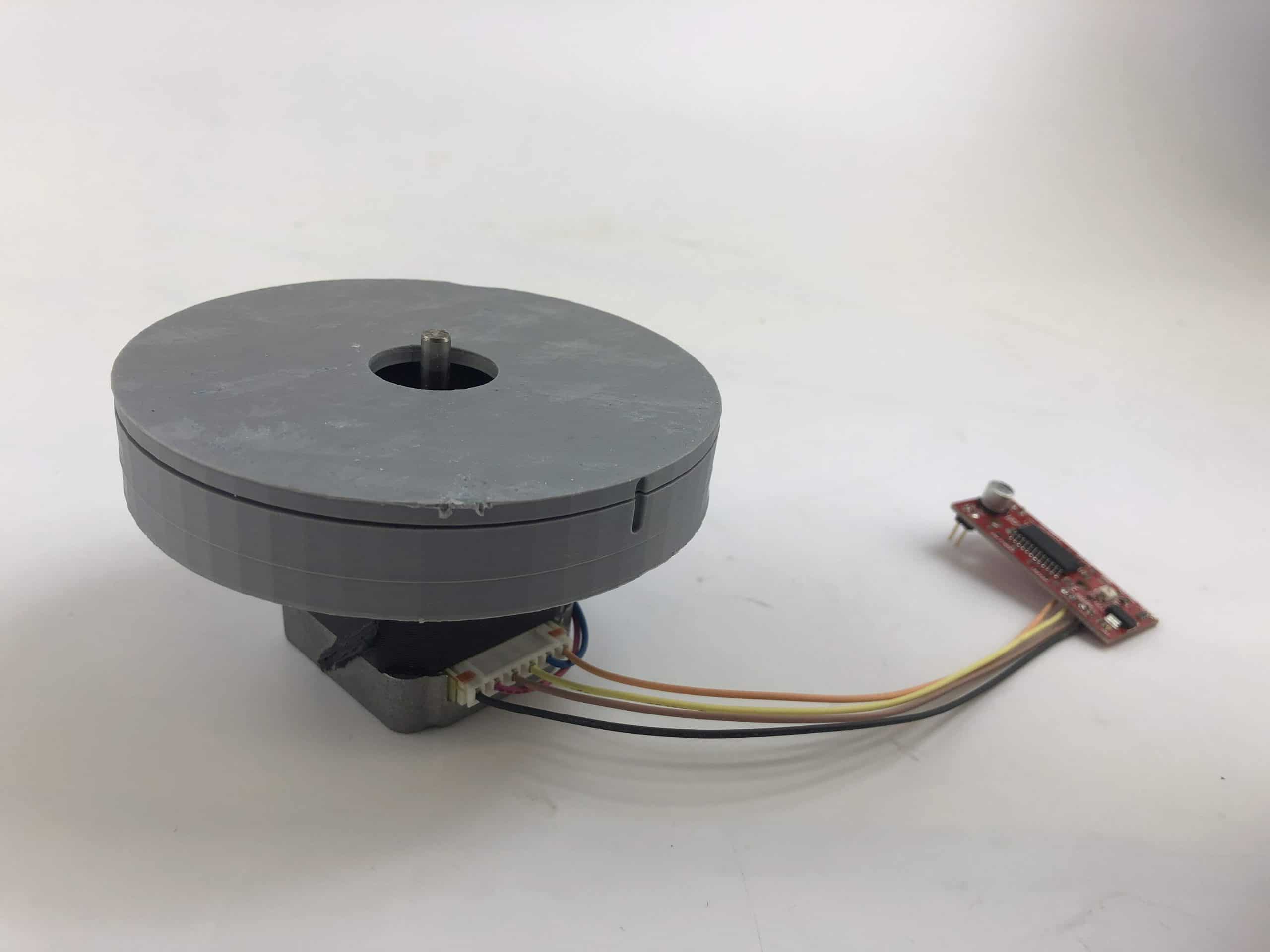
- The finished 3D print was not only difficult to separate from the printer, but also ran out of filament without stopping. As such the tallest features were cut off. However, the assembly with bearings, gears, and motor was largely a success. Although the CAM motion of this design matched the Solidworks CAM mate simulation, the printer tolerances were egregious on the gears resulting in very rigid rolling motion with a high degree of clogging.
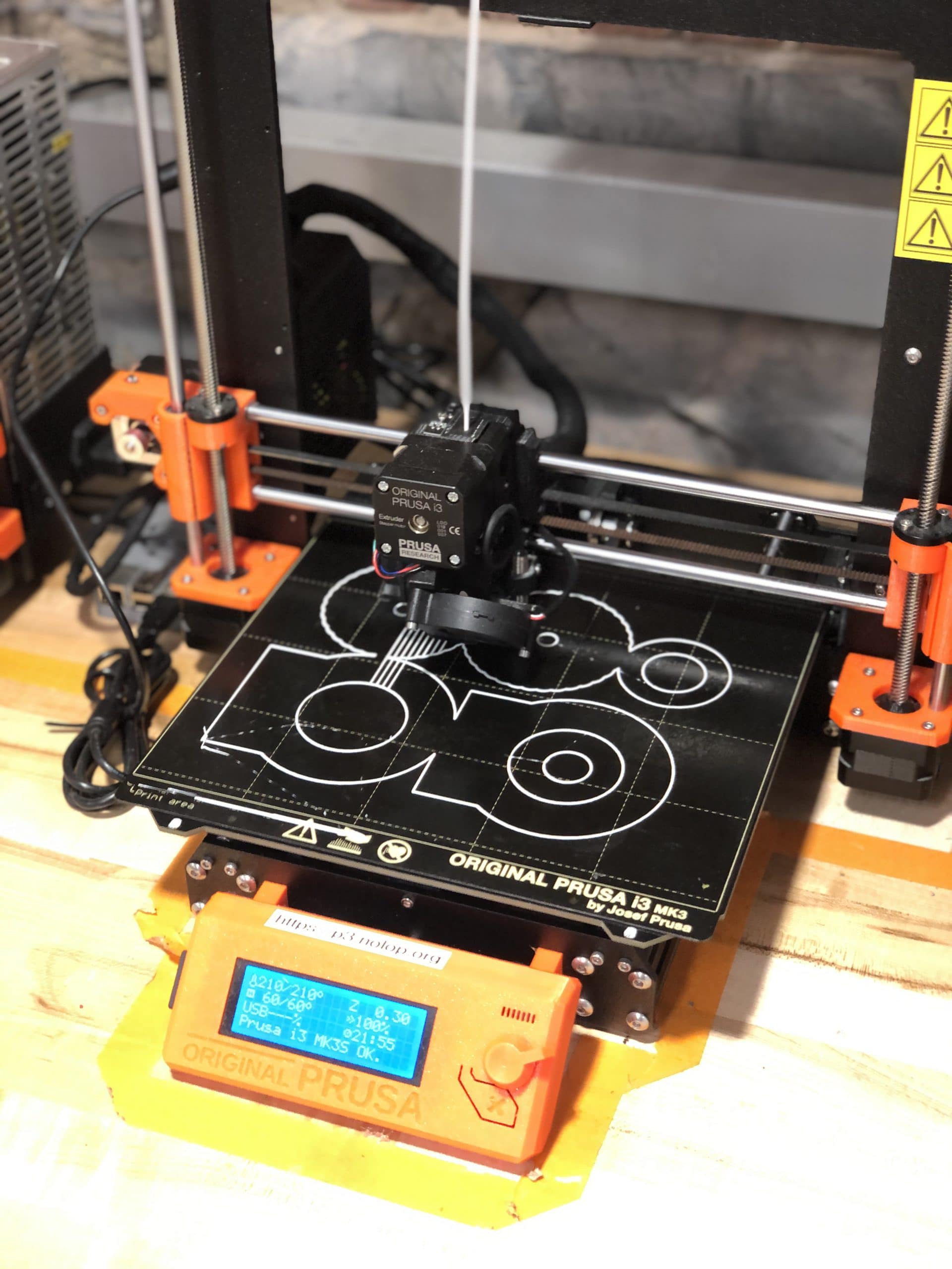
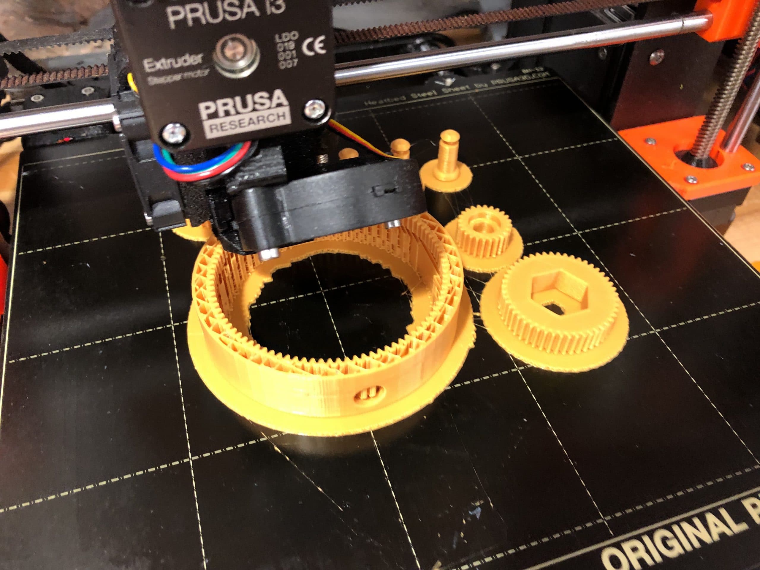
- I have since restarted the print on the more reliable Pruisa i3 and reassembled the device. Although gravity took a bite out of my 10% infill, fast print the overall structure was solid. Below are two videos that demonstrate the smooth, quiet reduction! The next step is to revise the gearbox around a more suitable motor and to make the entire assembly more friendly and less of an eyesore :-).
Design Developments
- Smoothed Geometry (Continuous Curvature where possible)
- Gearbox features mount point for carbon fiber frame
Electrical Developments
- BLDC Controller Selection
- VESC firmware requires significant revision to operate in closed loop.
- oDrive (almost identical in hardware to VESC) is suited for application.
- BLDC Motor Selection
- 200kV (200 Rotations per volt)
- 3Nm torque generated by phase current of 72 Amps
- Internal 120 Degree Offset Hall Effect Sensors for controlled startup
Manufacturing Developments
- FDM 3D printed gears, gearbox, and enclosure
- Integrated 200kV 3-Phase BLDC motor with M4 Screws
- Integrated 608 bearings
- Integrated XXXX bearings
- Integrated XXXX bearings
- Integrated M3x25 screws as roller pins
- Integrated Carbon fiber tubes


Revision 1 – Experiment with Cycloidal Drive
- Although there are no explicit mentions of hypocycloid gearbox designs in any reviews of contemporary exoskeleton solutions, their design and application in robotic industries leads me to believe that two of my “gold standard” exoskeleton products feature a variation of the cycloidal gearbox design.
- Advantages of these gears are their back-drivability, size and weight, efficiency, and low noise performance. A single stage can provide up to a 1:100 ratio reduction and dual stages can provide ratios in excess of 1:200. It is possible to is possible to eliminate the CAM vibration by modifying a single stage with a second gear that is a 180 degree phase shifted CAM shaft. This maximizes engagement and reduces vibrations and balances the gearbox. By designing two gear stages as single part, its possible to reduce the cost and complexity of the design.
- The first step is to parameterize a dual stage, compound hypocycloid gearbox with 180 degree CAM offsets (to eliminate vibrations and noise) and attempt to 3D print it. I have found a number of examples of such gearboxes on CAD repositories but few resources on their design and construction. I have found and processed several reports composed in English that also struggle to interpret the original design work published in Russian, but I have since managed to execute a design to iterate upon.
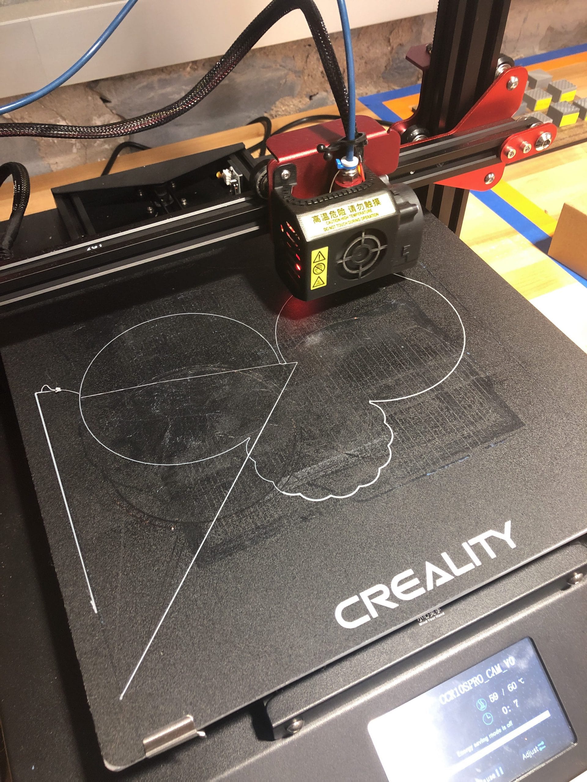
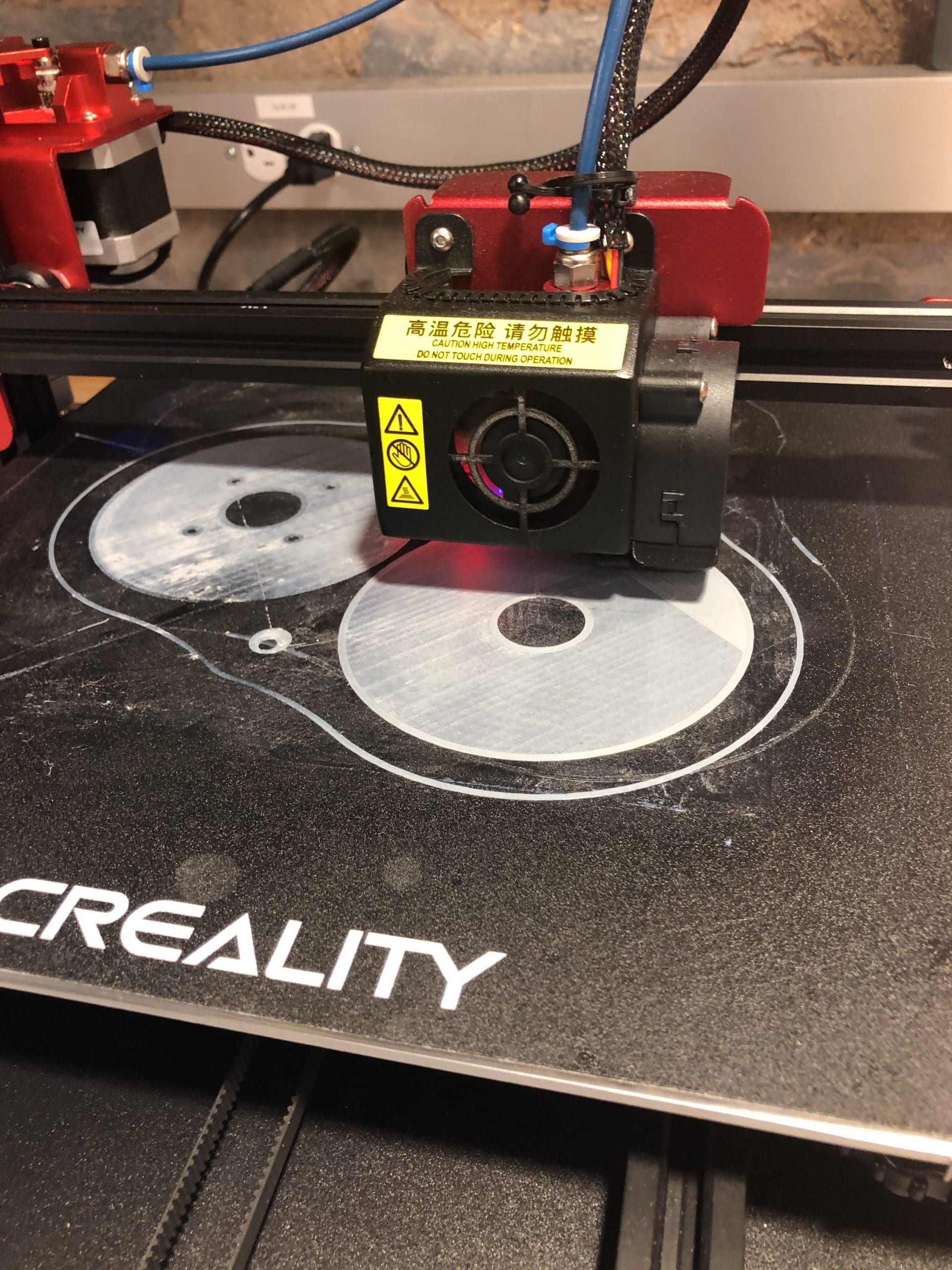
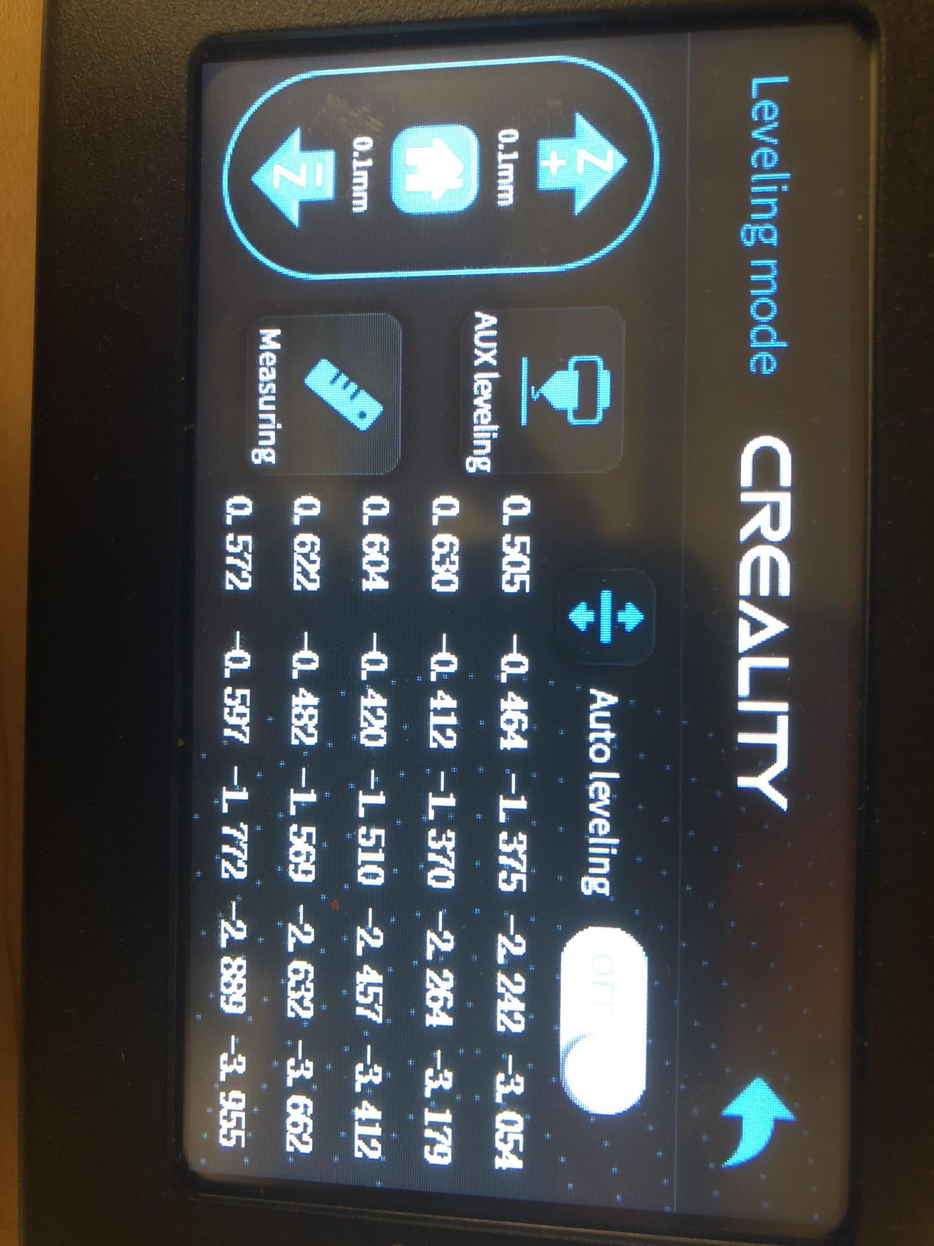
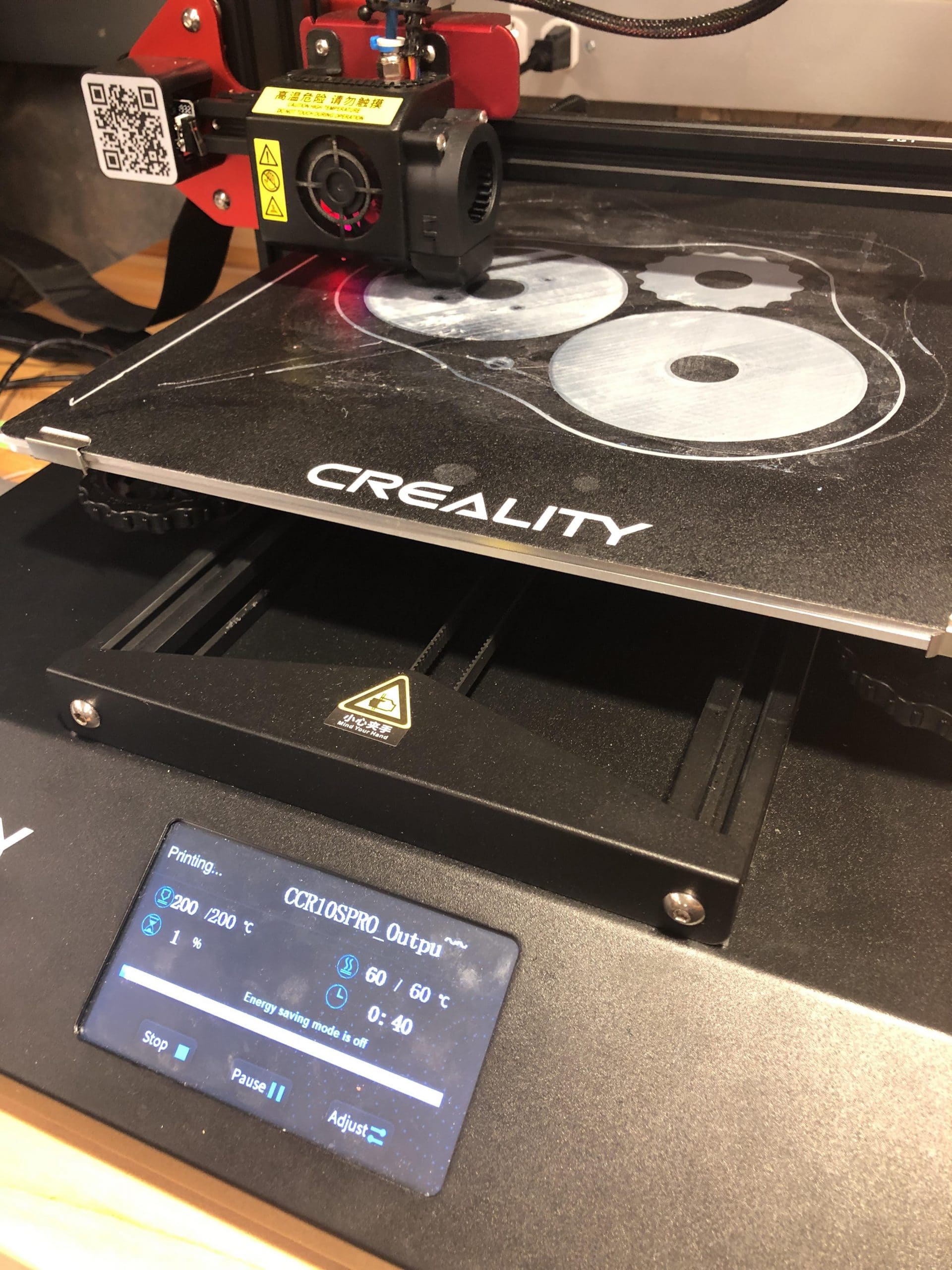
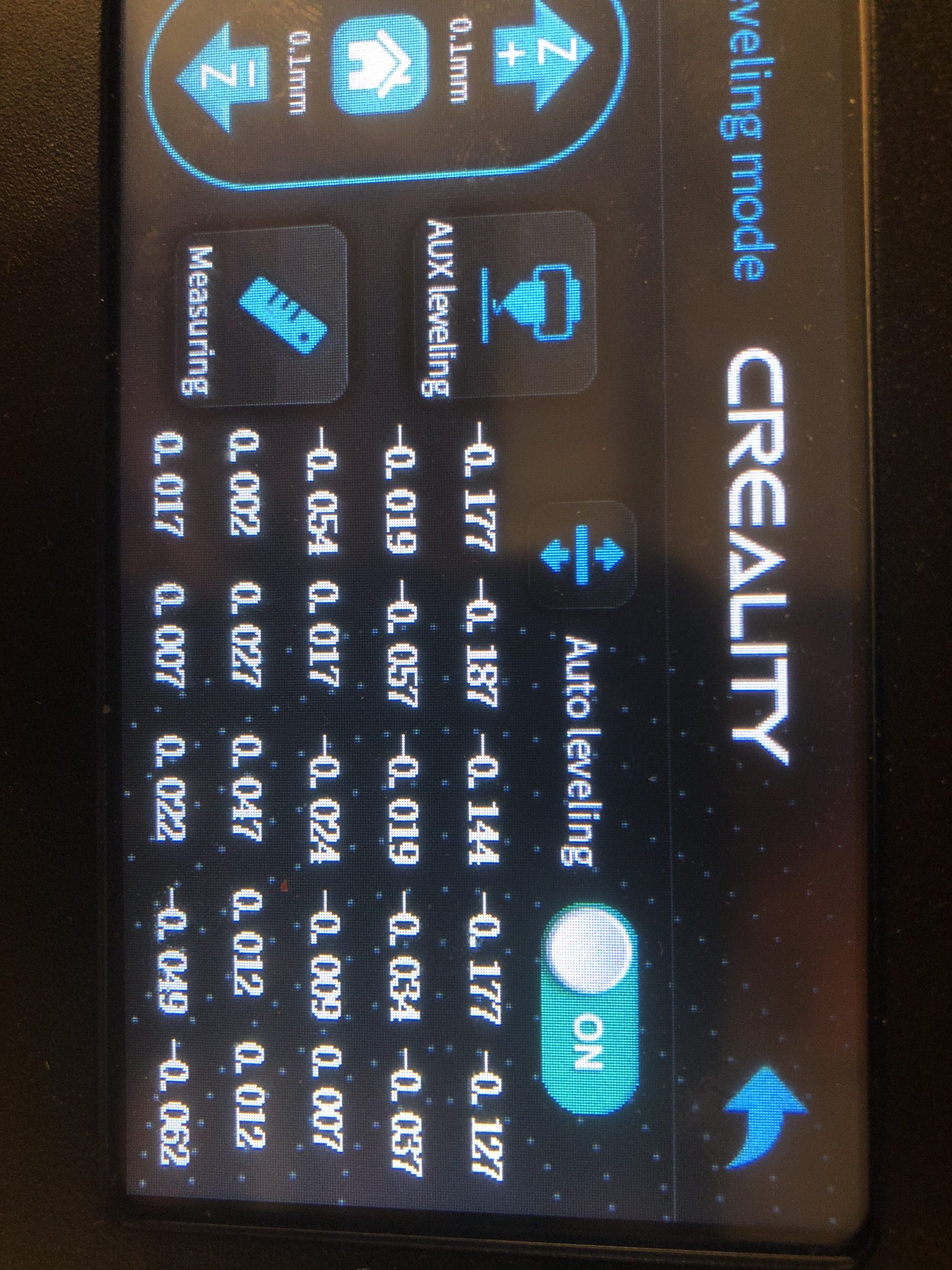
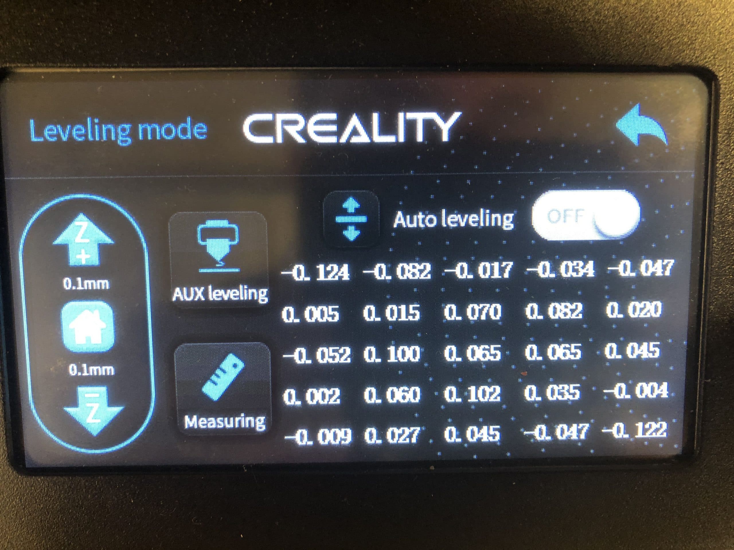
- This gearbox was a two day, one night adventure in setting up a brand new 3D printer in NOLOP and fighting with it for level prints and reliability. The Creality CR-10S V2 Pro was not the experience I expected after viewing so many reviews of the device online.
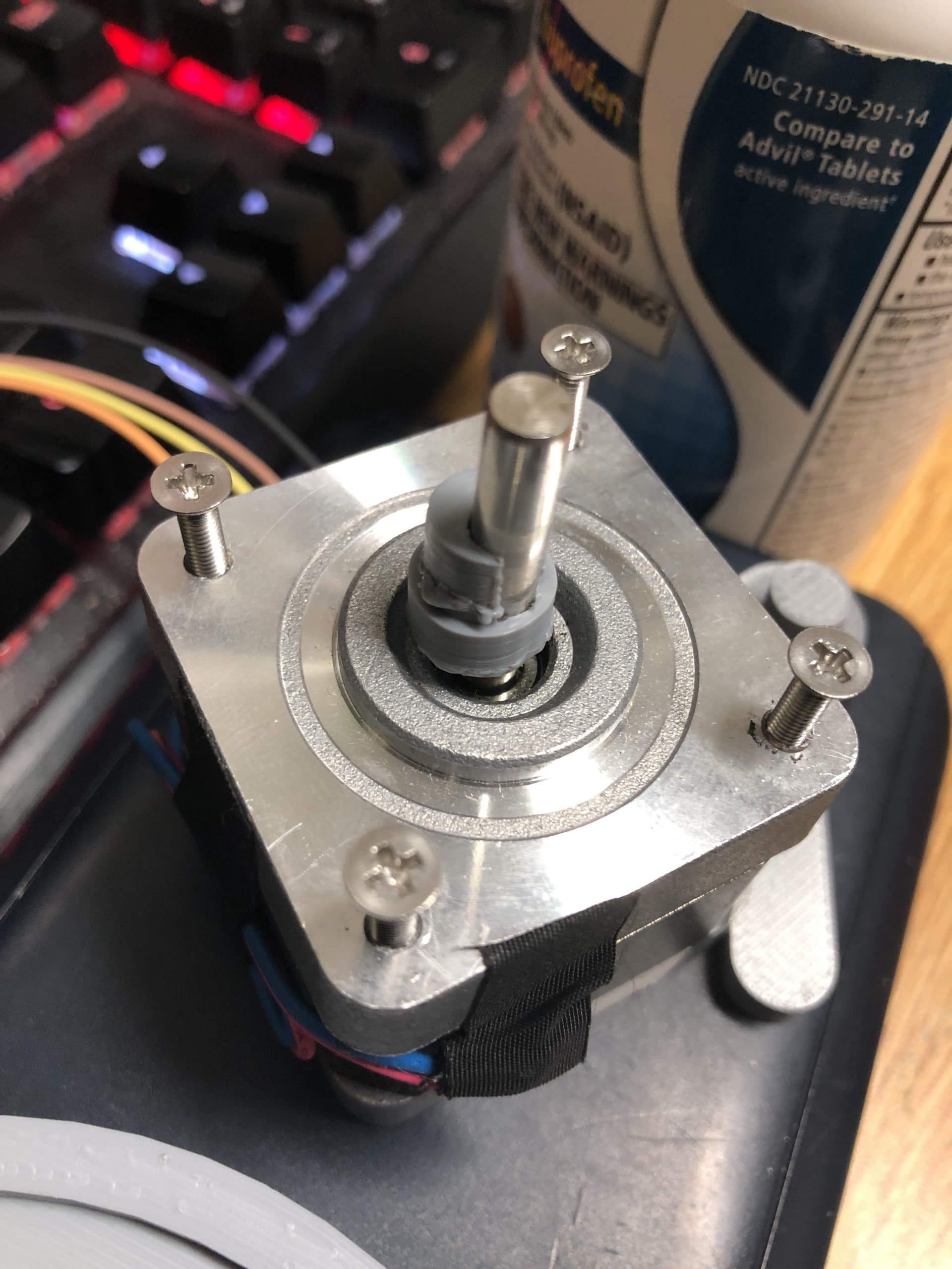
- The resulting products were printed ROUGHLY to scale with odd dimensional warping. The gearbox assembled with a stepper motor demonstrated the desired cycloidal motion during initial testing, but suffered from significant tolerance issues. Normal gearbox designs are more tolerant of dimensional issues, however the accuracy of the CAM shaft motion and clearance of gear lobes from the ring structure is understated. This may be the result of a small tooth lobe size, a decision that is my fault – however this iteration made clear to me that the desired motion could be produced. I believe that a revised gearbox can be designed with two independent stages to eliminate vibrations and promote smoother motion.
Design Developments
- Initial gearbox specifications
- Three part gearbox design ideal is not practical
- Integrated 180 degree offset gear to balance gearbox
Electrical Developments
- Stepper Motor for Demo
Manufacturing Developments
- Fixing the CR-10S V2 Pro
- Identified sensitivity to dimensional accuracy
")
")
")
")

")
")
")
")
")


")

")
")
")
")
")
")
")


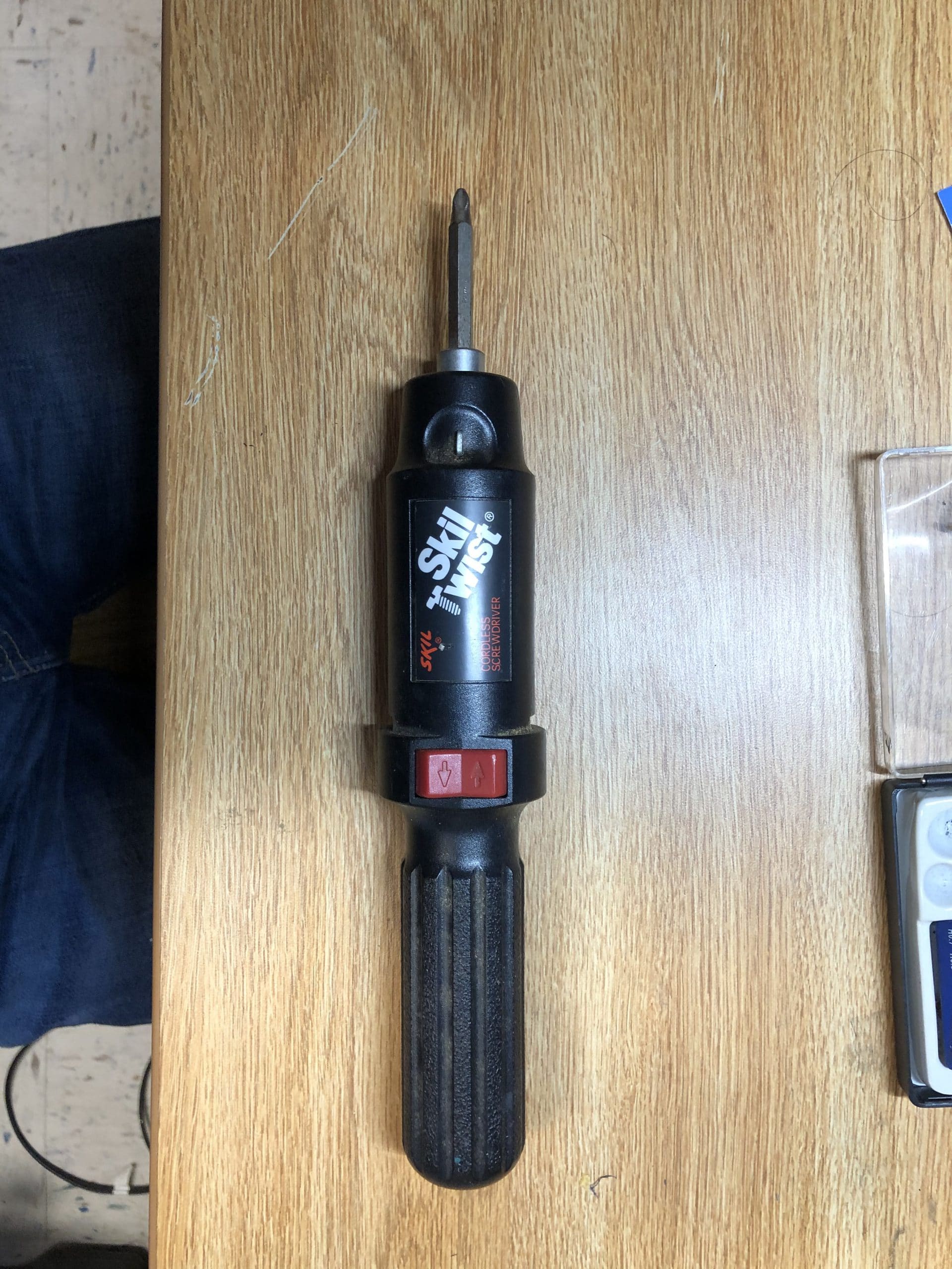
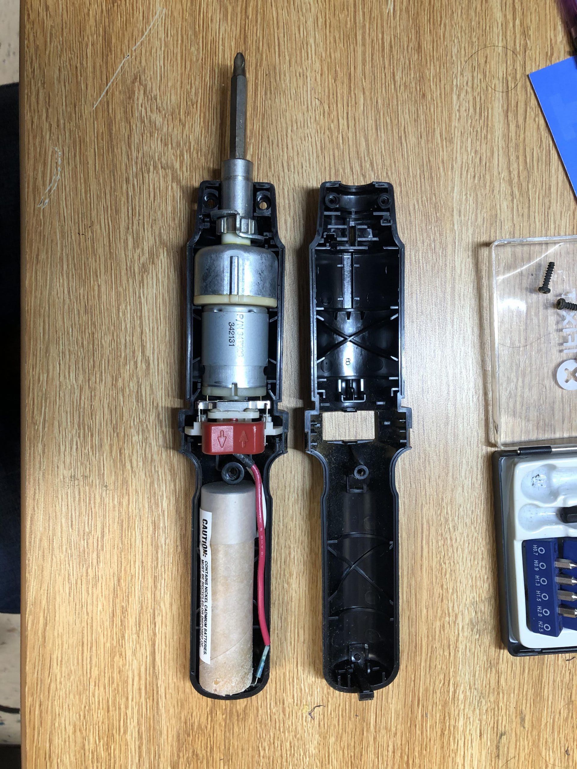
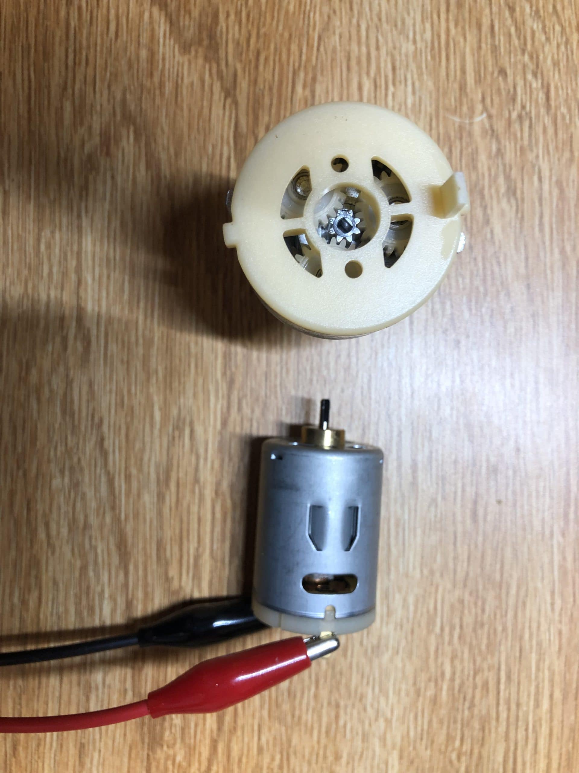
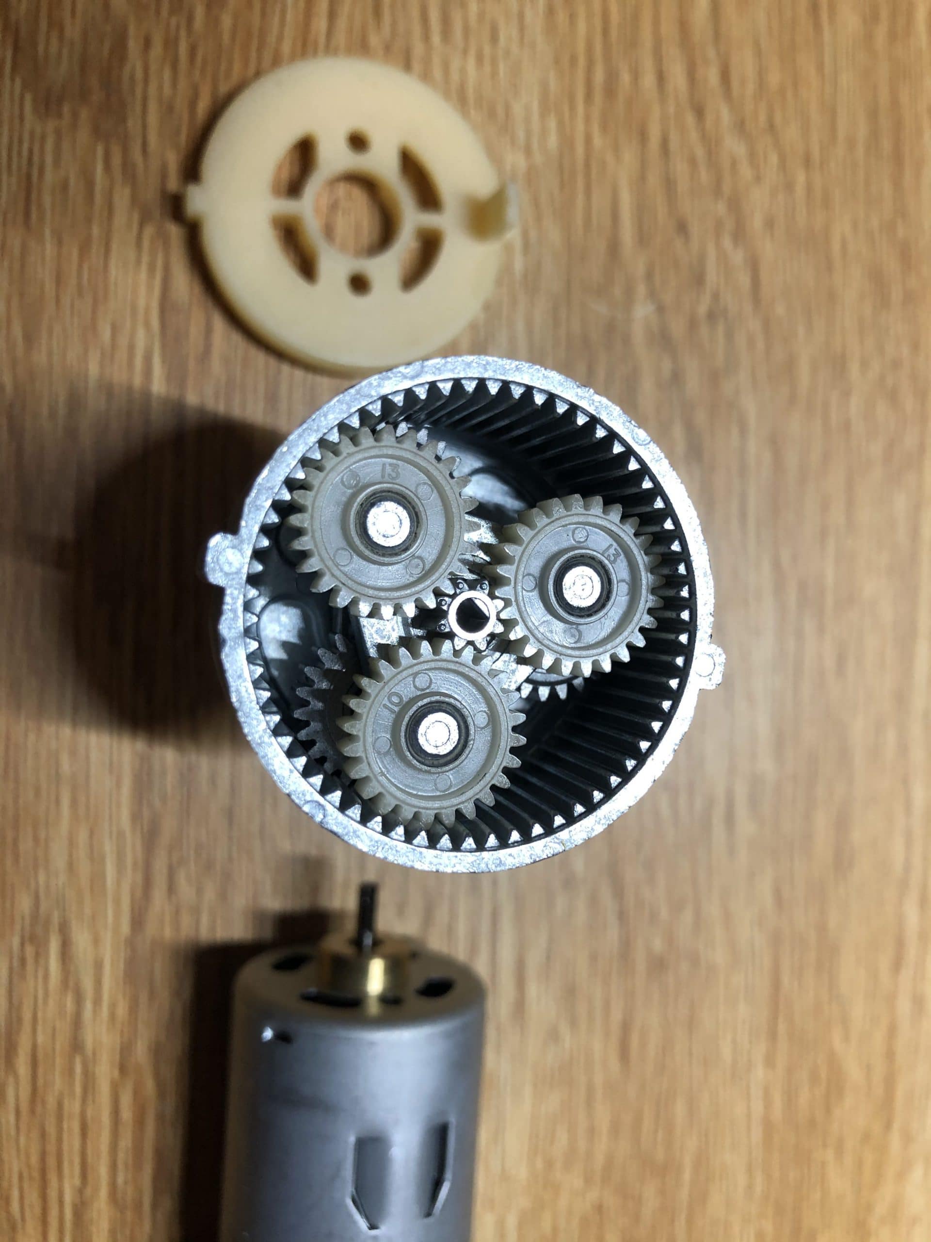
Reverse Engineering the Skil Twist
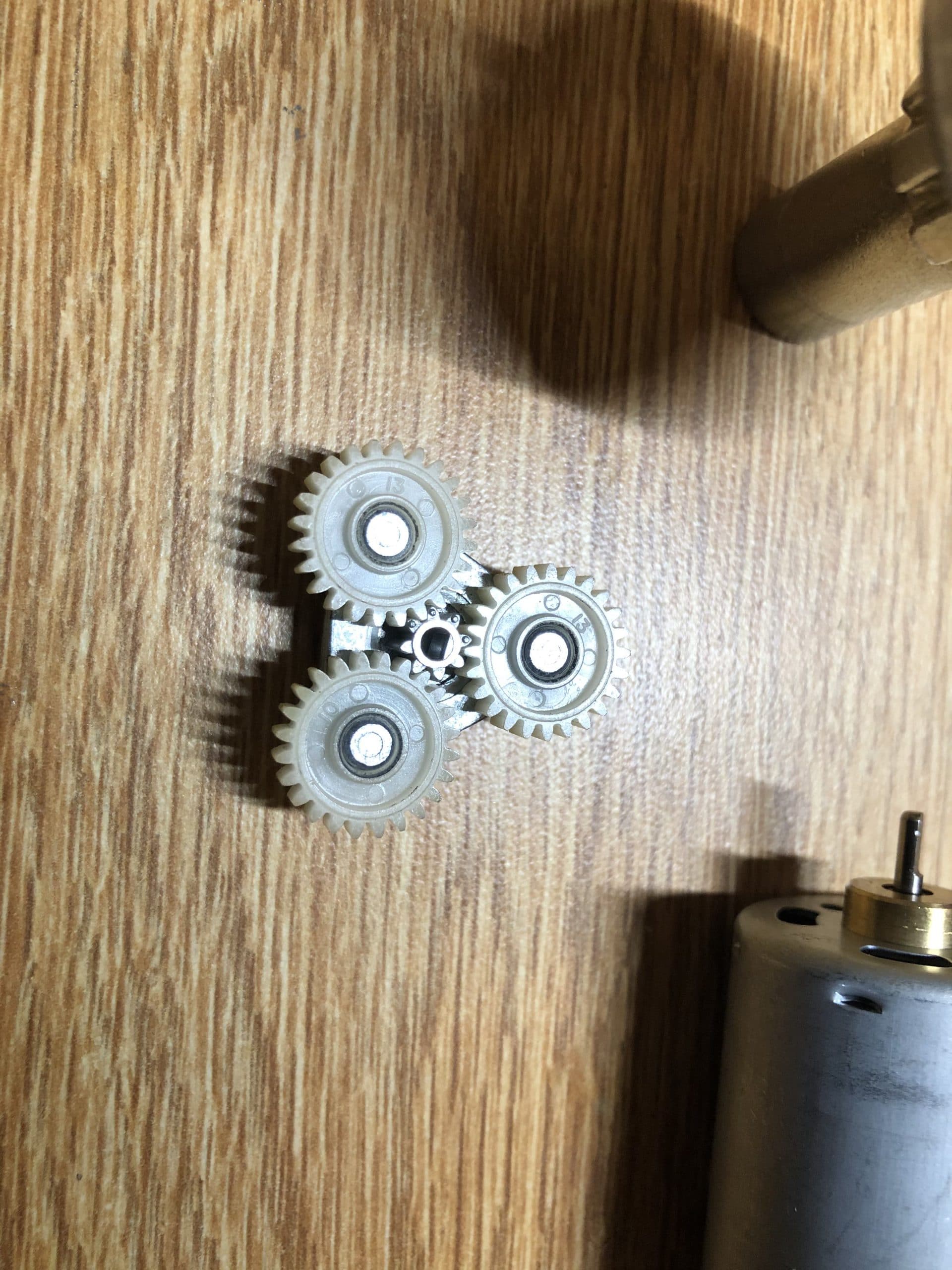
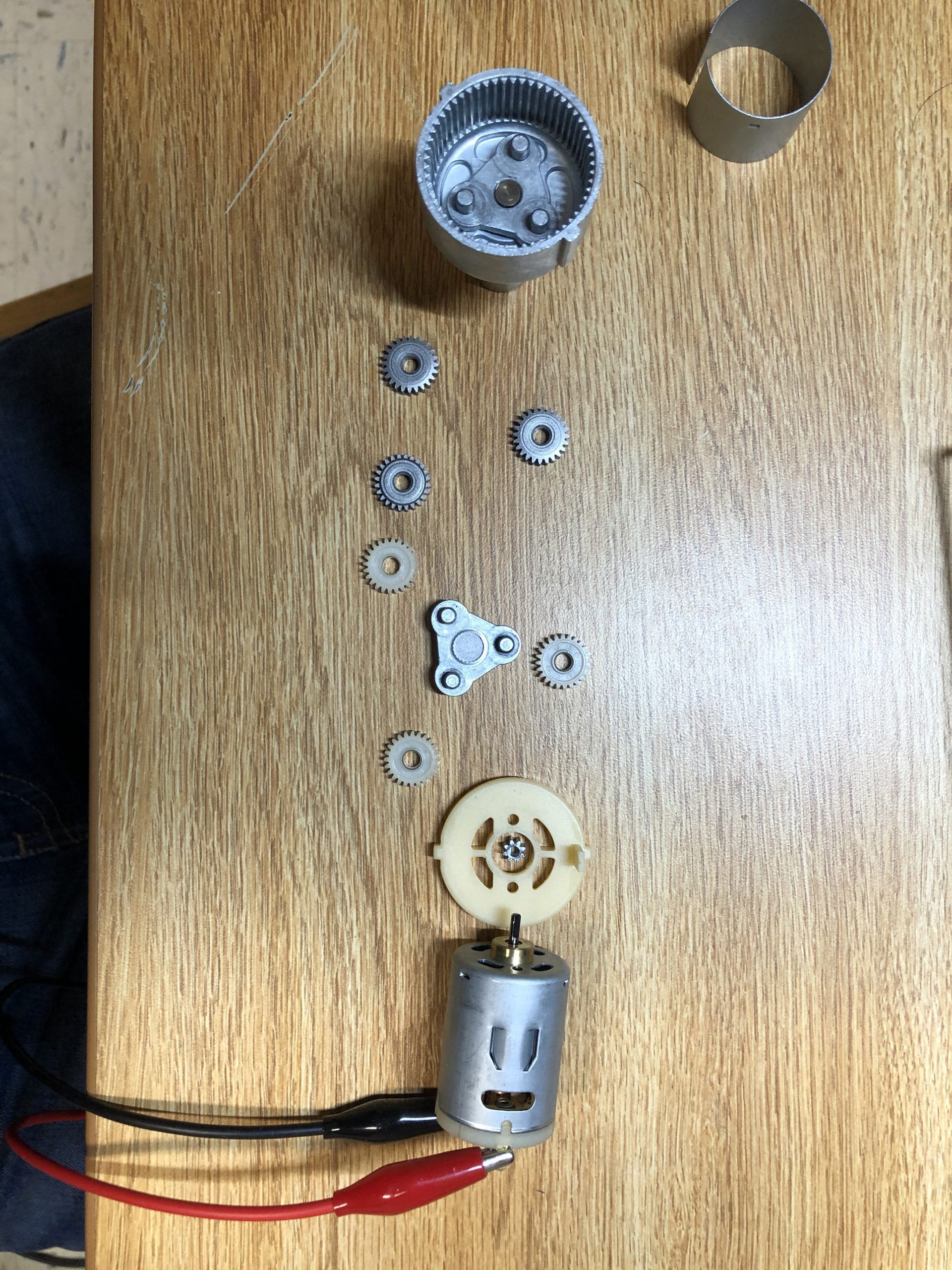
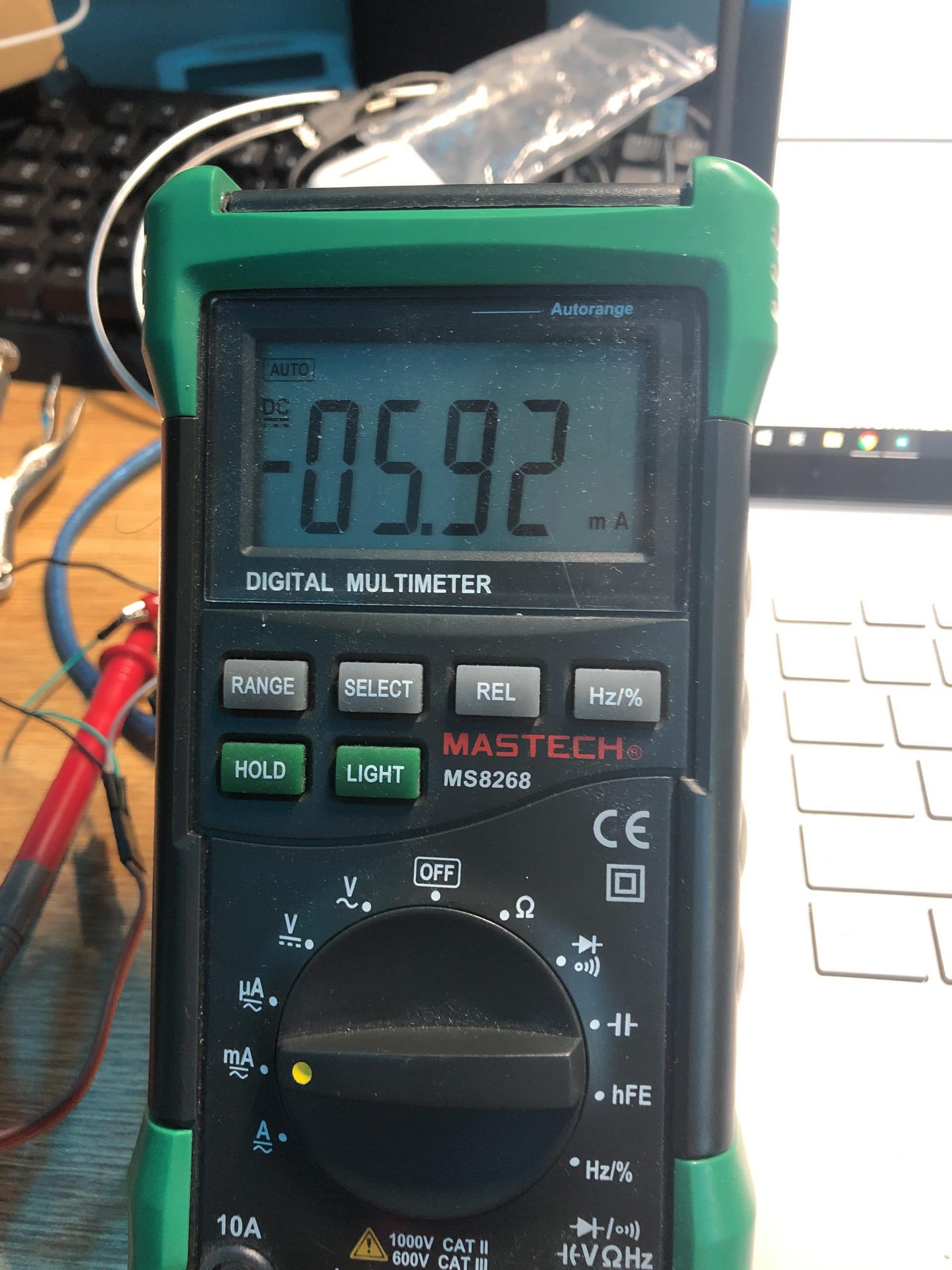
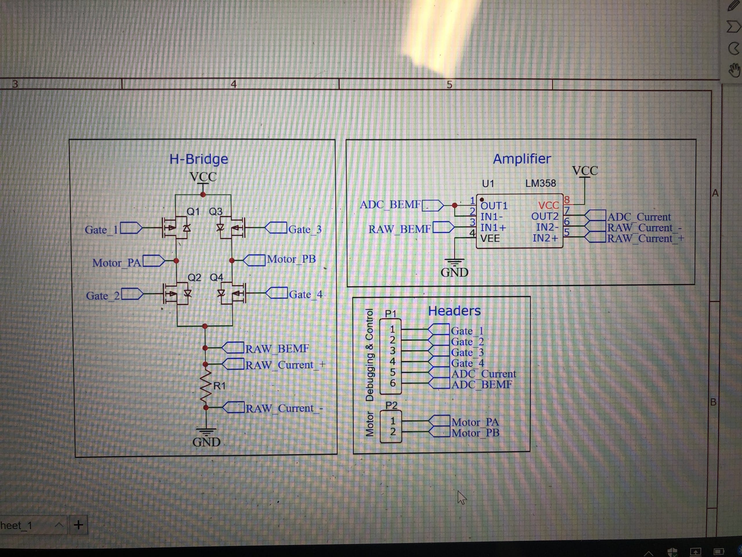
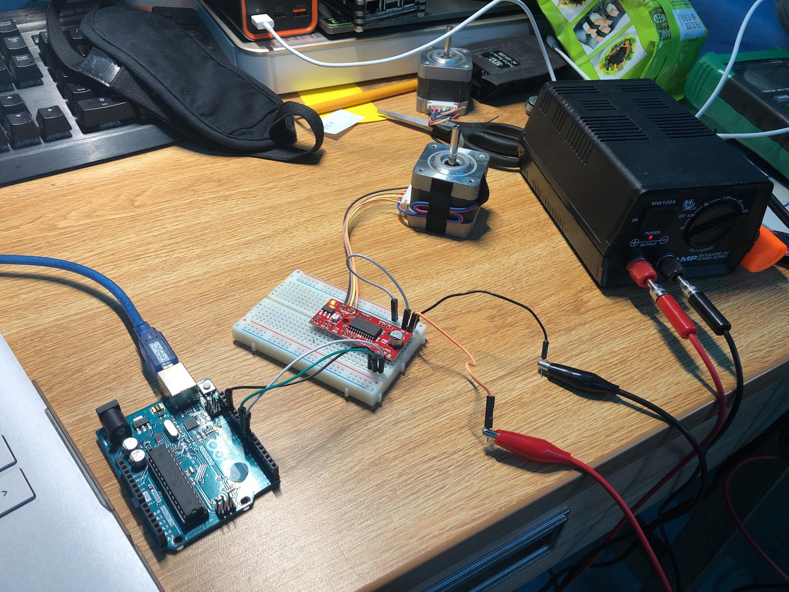
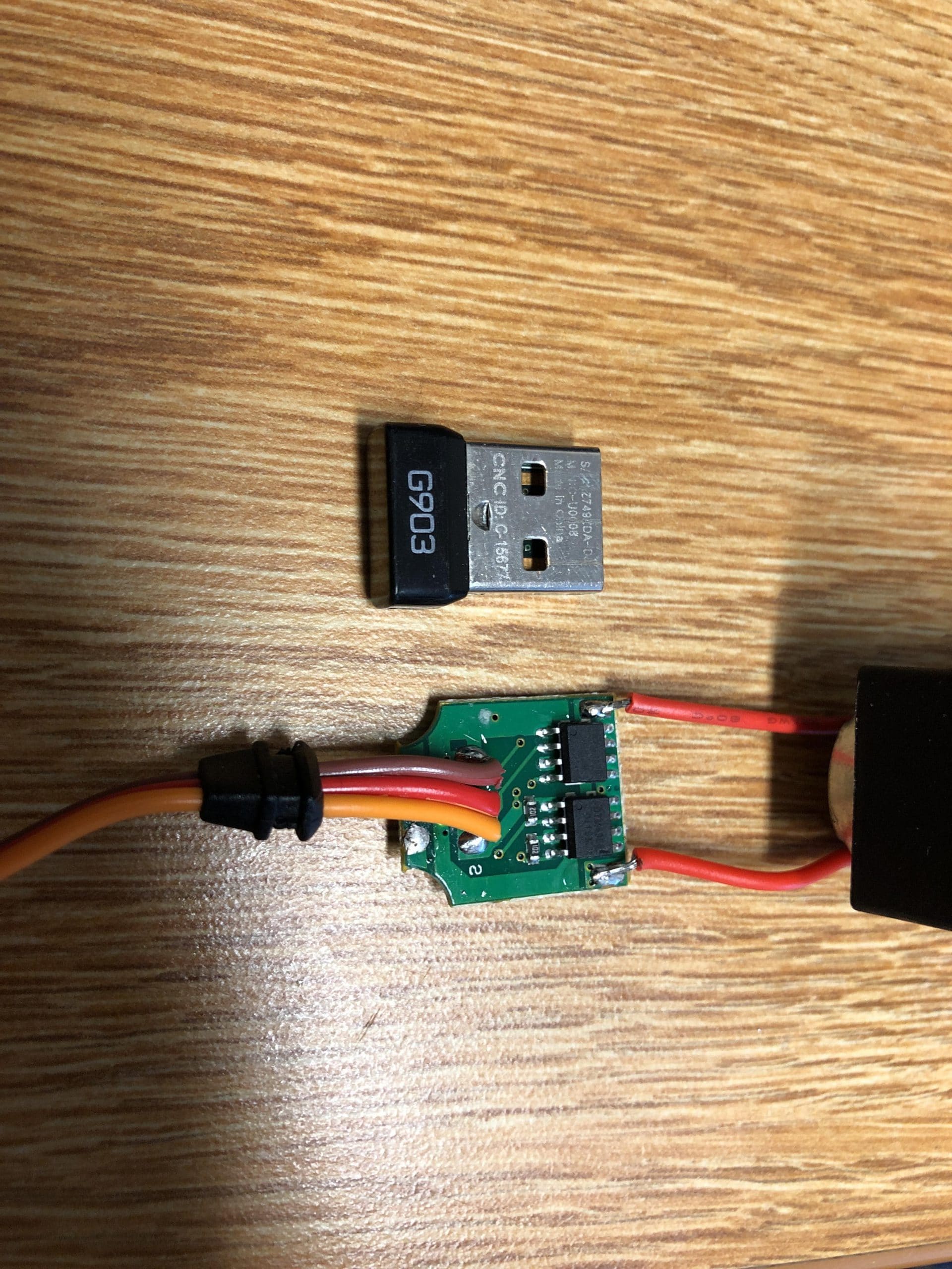
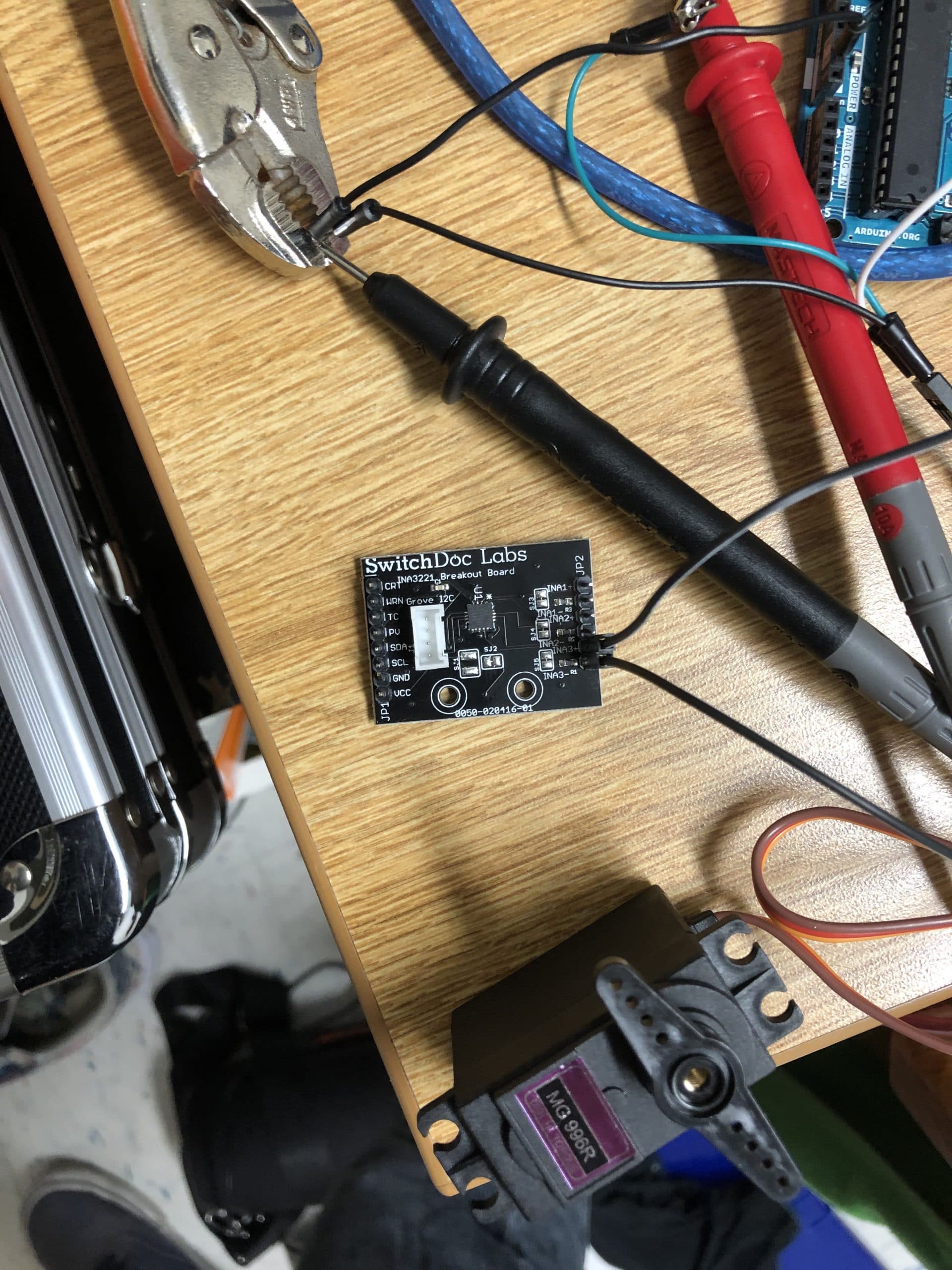
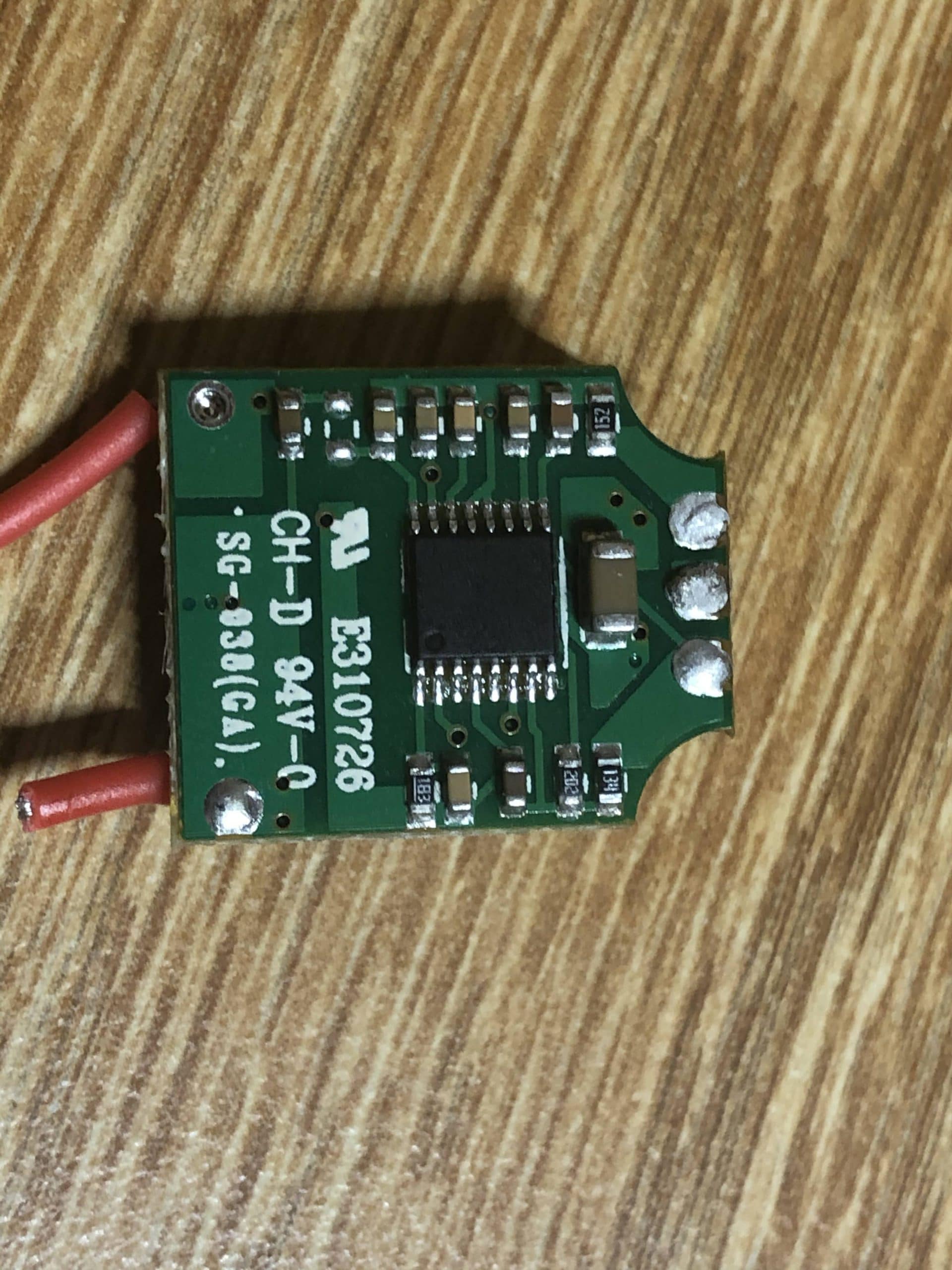
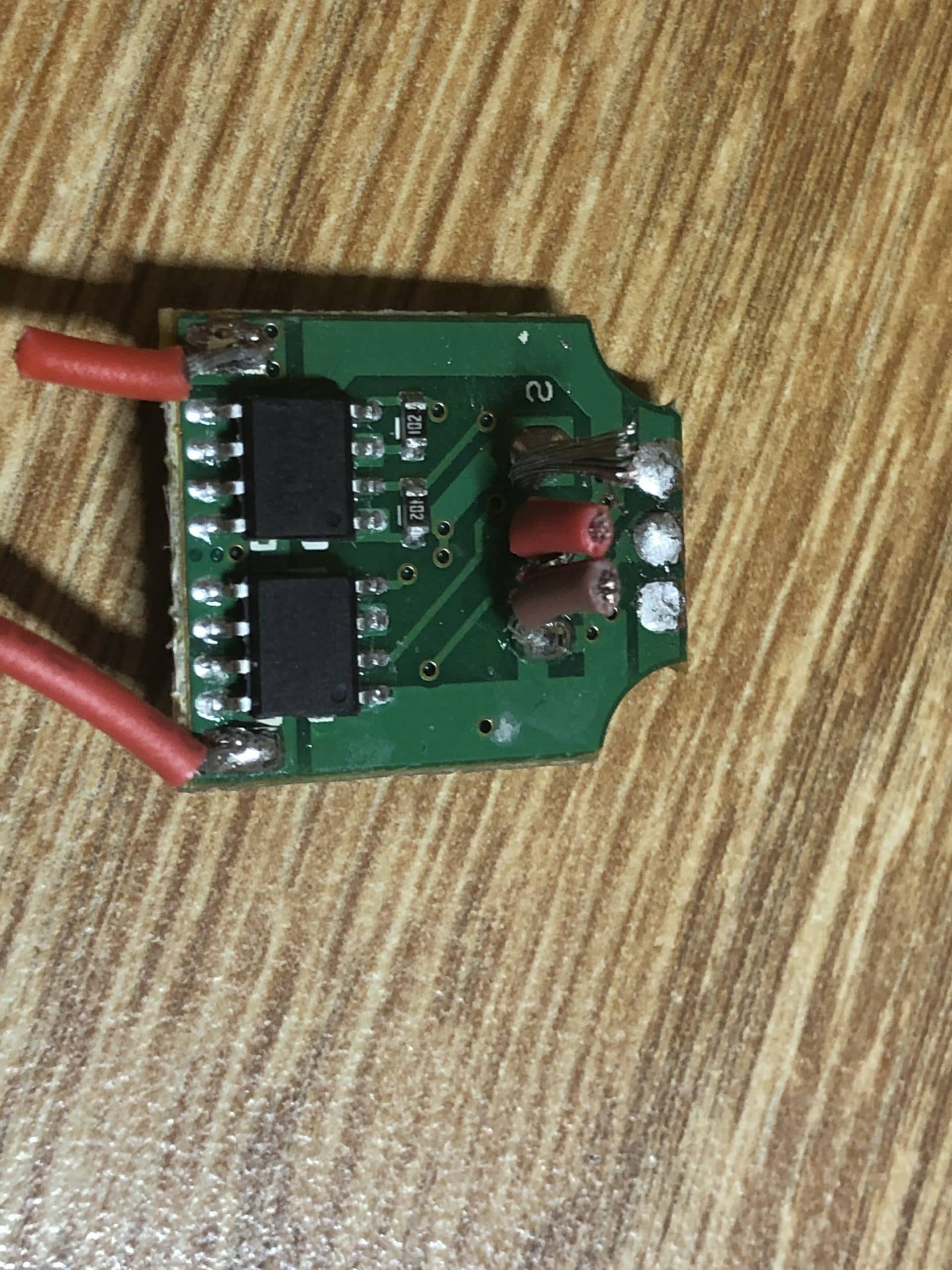
- The reverse engineering of the Skil Twist proved invaluable. Overall design simplicity and execution of the tool aside, the hybrid-material planetary gearbox has changed the direction of my actuator gearbox development. The pursuit of a small planetary gearbox and offset transmission gearbox solution for providing torque to the joint no longer seems practical for this application.Although the torque and noise generated by the 35mm OD gearbox and 28mm OD motor exceeded my expectations, back-drivability of the motor from the output shaft was limited. This is related to the high gearing ratio of the compound gearbox stage (3x Planets, 8T Sun, 25T Planet, 58T Ring, 1000:121). The reduction ratio can be modified to improve back-drivability at each stage, but implementing an easily back-driven system likely requires multiple sets and configurations of gears and parts that undermine modular design principles.This exploration has provided valuable insight into the direction of future gearbox development and has also provided a demonstration of “sensorless” torque and RPM approximation through current measurement and phase commutation properties.This prompted a directional change in the project to evaluate new actuator gearbox solutions. Harmonic Gear drives are common among several exoskeleton designs featured in a recent industry review, however their mechanism depends on the deformation of a consumable elastic part and is generally not a back-drivable solution.
Design Developments
- Initial gearbox specifications
- Three part gearbox design ideal is not practical
- Integrated 180 degree offset gear to balance gearbox
Electrical Developments
- Stepper Motor for Demo
Manufacturing Developments
- Fixing the CR-10S V2 Pro
- Identified sensitivity to dimensional accuracy


Revsion 0 – 3D Print Gearbox Failure
- A design flaw in the original concept art was corrected prior to prototyping. The concept gearbox’s threaded compound stages present a liability. A thread locking adhesive does not provide a permanent solution to the transmission of ring-gear torque to the gearbox stage assembly. Such torques result in risk of potential auto-disassembly which may be increased by thermal and loading conditions.To mitigate the risk, cantilever style snap-clips common to plastic assemblies are implemented around the perimeter where threading was previously.The assembly was printed thrice at original scale and once at 3x scale on Pruisa i3 printers in Tufts NOLOP from PLA plastic.The first print at scale was configured with default settings. The outer diameter of 28mm was accurate, however the tooth profile of the gears were entirely lost. This is because several model features were smaller than the resolution of the default slicer settings. For example, the teeth were smaller than the 1mm shell which meant that they would be enlarged during the printing process. Likewise, the 0.8mm top/bottom thickness affected the vertical height of some regions. Although the parts were not functional, the fit was exceptional within the carbon fiber tube. I attempted two additional prints with higher resolution slicer settings and with similar results.3x scale print allowed me to evaluate the performance of the gears and cantilever style clips. At this scale, however, part shrinkage during the cooling process was more significant and the planetary carrier and gears fell short of my expectations. The gears meshed well outside of the assembly, indicating that the tooth profiles were clean and effective. The cantilever style clips perform exceptionally well at this scale, thus further refinement based on Castigliano’s Theorem or FEA can tune the deflection of the clips during assembly to prevent fracture or premature wear.Professor Leisk recommended an exploration of the \”Skil Twist Cordless Screwdriver\” to gain insight into the design of similarly sized, planetary gearboxes.
Design Developments
- Initial gearbox specifications
- Three part gearbox design ideal is not practical
- Integrated 180 degree offset gear to balance gearbox
Electrical Developments
- Stepper Motor for Demo
Manufacturing Developments
- Fixing the CR-10S V2 Pro
- Identified sensitivity to dimensional accuracy

")

")
")
")
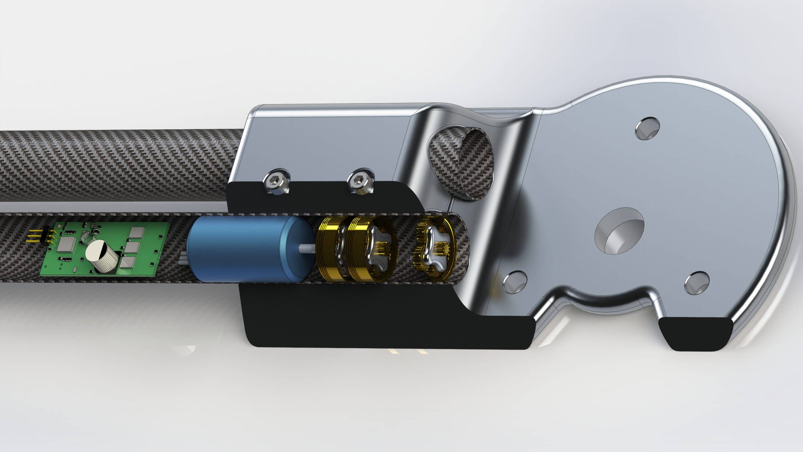
Concept – Gearbox in the tube + BLDC Inrunner + Mini PCB
-
The core function of the actuator is to convert electrical energy into kinetic energy. The following requirements affect the selection of materials, motor, and gearbox design.
- The design needs to be robust because it is cyclically loaded and its failure results in the loss of motion or control at an otherwise augmented joint.
- The design needs to be scalable as different operators have different needs.
- The design needs to be as compact and lightweight as possible as it will affect aesthetics and increase inertia.
- The design needs to be high-efficiency as its power consumption is proportional to the required power supply.
- The design needs to be quiet and isolated from the user and environment.
- The design needs to be back-driveable so that external forces, such as gravity, can provide motion without powered actuation.
- The original design concept concealed the control circuit, motor, and modular gearbox within a carbon fiber, structural element of the frame. Reduction scaling of the motor is possible through the addition or removal of gearbox stages from the compound gearbox by screwing the ring gears together. The inertial profile of this solution is defined by the weight distribution over a greater distance rather than at the joint itself. The encasement of the actuator system within the structural element provides user and environmental isolation with the added bonus of RF/EMI protection within the carbon fiber tube body.To provide smooth forward and reverse motion, the back-drivability of the gearbox must be taken into consideration. The inversion of torque inputs and outputs of the gearbox shall not be associated with changes in rotational resistance. A planetary gearbox delivers torque efficiently in a small space without generating unbalanced thrusts and forces. The rotation of the sun gear results in the rotation of the planetary carrier because the ring gear is held stationary. This gearbox provides 1:3.33 reduction per stage, thus allowing a 10,000 RPM low torque motor to provide high torque at 2 RPM in only 7 stages.
Design Developments
- Initial gearbox specifications
- Three part gearbox design ideal is not practical
- Integrated 180 degree offset gear to balance gearbox
Electrical Developments
- Stepper Motor for Demo
Manufacturing Developments
- Fixing the CR-10S V2 Pro
- Identified sensitivity to dimensional accuracy


")

")


